00197498-03_UM_SiplaceCA-Serie_EN.pdf - 第194页
3 Technical Data User Manual SIPLACE CA-Series 3.14 Flexible Dual PCB Conveyor From softwar e version SC.708.0 Edition 12/2014 EN -DRAFT 194 3.14.7.2 Synchronous T ransport Mode Description 3 In synchronous mode, two PCB…
User Manual SIPLACE CA-Series 3 Technical Data
From software version SC.708.0 Edition 12/2014 EN -DRAFT 3.14 Flexible Dual PCB Conveyor
193
3
Fig. 3.14 - 3 Transport modes
3.14.7.1 Asynchronous Transport Mode
Description 3
In asynchronous mode, only one PCB in a transport track is processed. At the same time, another
PCB in the second transport track is moved into the placement position. This saves the full con-
veying time of one PCB, thus considerably increasing performance, particularly for PCBs with a
short cycle time.
Function 3
Once the machine has received the job data (panel, setup), the PCBs on the feeding belts are con-
tinuously transported to the available processing belt (provided that the processing belt is free)
throughout the placement operation. The placement sequence starts as soon as a PCB has
moved onto the processing belt. The PCBs are processed one after another.
If the placement sequence is interrupted, the conveyor interface will be disabled and the PCBs
currently on the processing belts will be completed.
The conveyor interface is disabled or enabled simultaneously for both transport tracks.
3
3
Synchronous Transport Mode
Asynchronous transport mode

3 Technical Data User Manual SIPLACE CA-Series
3.14 Flexible Dual PCB Conveyor From software version SC.708.0 Edition 12/2014 EN -DRAFT
194
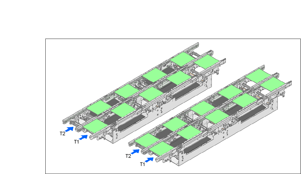
3.14.7.2 Synchronous Transport Mode
Description 3
In synchronous mode, two PCBs of the same size are moved into the placement position at the
same time. They must be processed as a common panel.
This facilitates the processing of a board upper and underside in one line. The time needed to
transport the board is reduced as two boards are always transported at the same time. It also en-
sures better utilization of the nozzle configuration.
Function 3
PCBs on conveyor tracks 1 and 2 are moved synchronously onto the conveyor sections (i.e. the
conveyors are controlled synchronously, but independently of one another). The components to
be placed on conveyor tracks 1 and 2 must be organized into a panel via two subpanels. (See the
SIPLACE Pro user manual).
If only one conveyor track (or center conveyor) is full when the placement sequence starts, the
subpanel on this section will be identified as “not for placement”.
Restrictions 3
If the dual conveyor is operated in synchronous mode, the ‘PCB whispering down the line’ option
is deactivated. PCB barcode operation is not supported in this mode. The "Global bad fiducial"
option cannot be used.
3.14.8 Dual Conveyor Control with Single Function Menu
The online help contains information on controlling the dual conveyor and on the Single Functions
menu.
3
3
3.14.9 Automatic Width Adjustment for Dual Conveyors
When the command is received, the conveyors are set to the desired width one after another. Dif-
ferent widths are possible.
See the Online Help for detailed information about changing the conveyor track width.
User Manual SIPLACE CA-Series 3 Technical Data
From software version SC.708.0 Edition 12/2014 EN -DRAFT 3.15 PCB Warpage
195
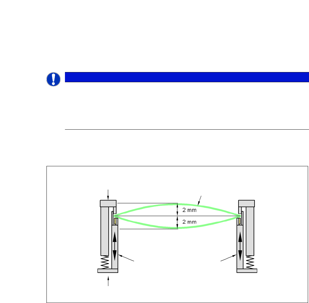
3.15 PCB Warpage
3
3.15.0.1 PCB Warpage During Transportation
PCB warpage across the direction of travel max. 1 % of the PCB diagonal, but not exceeding 2 mm
3
PLEASE NOTE
Vacuum Tooling for Thin Substrates
Vacuum tooling is not essential. However, it is needed for thin substrates, to ensure place-
ment accuracy and error-free handling.
Use the vacuum tooling option for thin substrates (less than 0.7 mm), to maintain the
prescribed PCB warpage.
Fixed clamped edge
Movable clamping device
Printed circuit board
Conveyor side