00197498-03_UM_SiplaceCA-Serie_EN.pdf - 第20页
1 Introduction User manual SIPLACE CA-Series 1.1 Machine Overview From software version SC.708.0 Edition 12/2014 EN -DRAFT 20 1.1 Machine Overview 1.1.1 SIPLACE CA4 1 Fig. 1.1 - 1 SIPLACE CA4 placement machine with SIPLA…

User manual SIPLACE CA-Series 1 Introduction
From software version SC.708.0 Edition 12/2014 EN -DRAFT
19
1 Introduction
This user manual is a guide or reference work for operating and setting up the SIPLACE
®
CA-
Series placement machines.
The CA-Series placement machine are available as SIPLACE CA4 with 4 gantries.
This document is the original user manual.
The header of each chapter contains the release and software version, to which this manual ap-
plies.
1 Introduction User manual SIPLACE CA-Series
1.1 Machine Overview From software version SC.708.0 Edition 12/2014 EN -DRAFT
20
1.1 Machine Overview
1.1.1 SIPLACE CA4
1
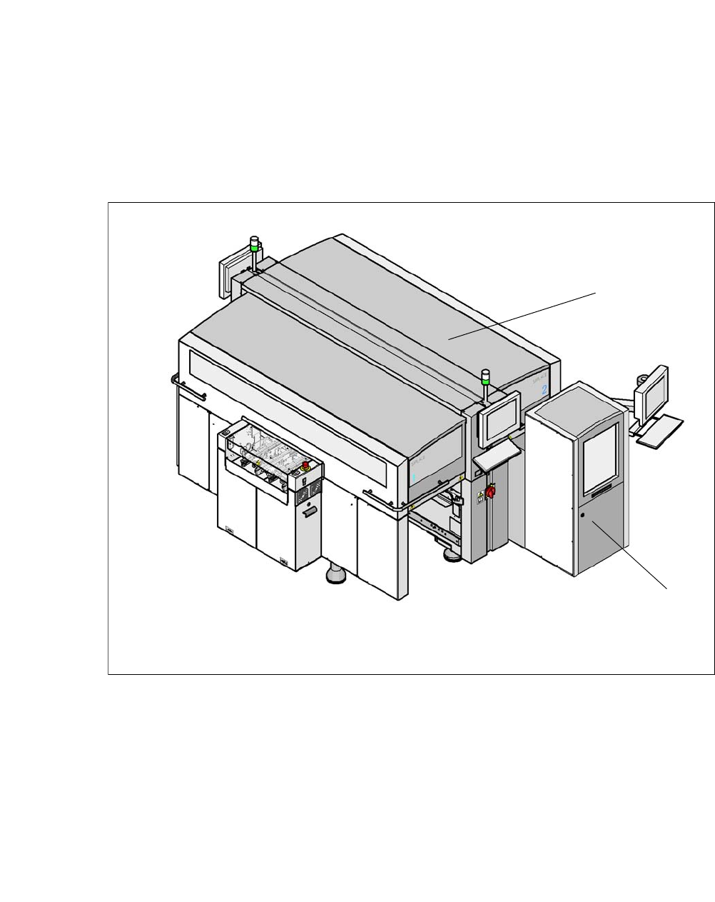
Fig. 1.1 - 1 SIPLACE CA4 placement machine with SIPLACE Wafer System (SWS)
(1) SIPLACE CA4
(2) SIPLACE Wafer System (SWS)
The CA4 placement machine has four gantries, two for each placement area (PA). All the gantry
axes are driven by linear motors. The gantry axes can be positioned quickly and accurately in the
X and Y directions. The gantry arms are lightweight constructions made from a highly rigid carbon
fiber composite material.
The placement machine has at least one SIPLACE Wafer System (SWS) at one of the four loca-
tions, so that dies can be placed from wafers.
1
2
User manual SIPLACE CA-Series 1 Introduction
From software version SC.708.0 Edition 12/2014 EN -DRAFT 1.2 Machine Description
21
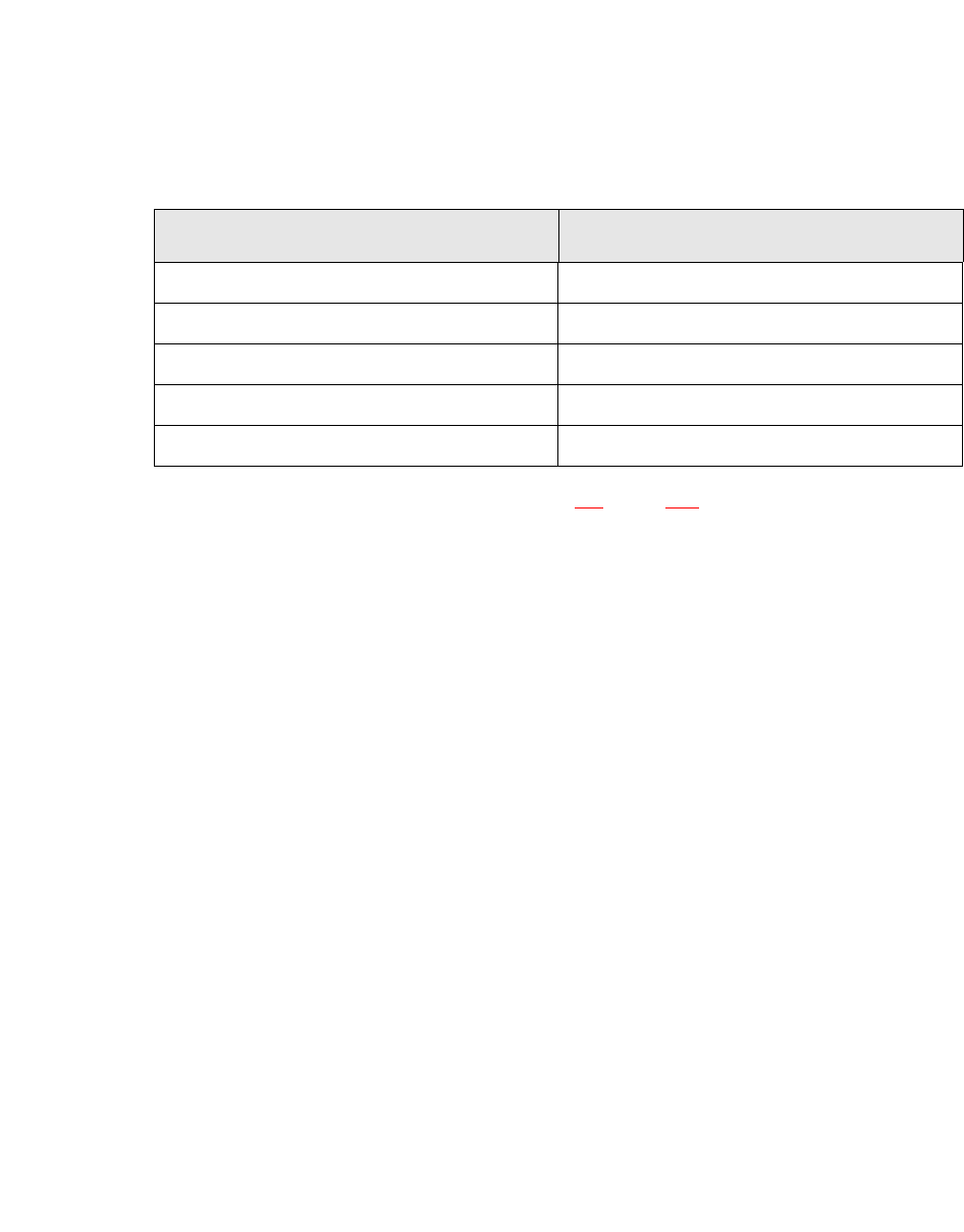
1.1.1.1 Overview of Placement Head Configuration
1
The performance data can be found in section 3.1, page 121.
1.2 Machine Description
The SIPLACE CA placement systems impress with high configuration flexibility, top placement
performance and maximum precision. The SIPLACE CA can place bare dies directly from the wa-
fer, by using the flip chip or die attach process, and can also place the entire SMD spectrum cov-
ered by the SIPLACE X machines.
Two placement methods are used on the placement machines:
– The Collect&Place method for high-speed placement of standard components
– The Pick&Place method for fast placement of special components in the fine-pitch and super
fine-pitch range
The SIPLACE CA is based on the well-proven hardware and software of the SIPLACE X machine.
Various modifications to the hardware and software enable the SIPLACE CA to operate with an
innovative new design: the SIPLACE Wafer System (SWS), which uses the same user interface
for both SIPLACE Pro and the station software. The placement machine has at least one SI-
PLACE Wafer System (SWS) at one of the four locations, so that dies can be placed from wafers.
The Siplace CA can also be operated without the SWS, in the same way as an X-Series machine.
This makes the components (dies) directly available to the placement head, in so-called wafers.
The gantries that are driven by linear motors can be positioned fast and precisely in X and Y di-
rection. Each gantry has one placement head.
Placement area 1 Placement area 2
C&P20 M / C&P20 M C&P20 M / C&P20 M
C&P20 M / C&P20 M CPP / CPP
CPP / CPP CPP / CPP
C&P20 M / C&P20 M CPP / TH
CPP / CPP CPP / TH