00197498-03_UM_SiplaceCA-Serie_EN.pdf - 第208页
4 SIPLACE Wafer System (SWS) User Manual SIPLACE CA- Series 4.1 Functions From software version SC.708.0 Edition 12/2014 208 4.1.5.2 Flip Chip Segment 1 (Z Dire ction) 4 Fig. 4.1 - 7 Flip Chip Segment 1 (Z Direction) (1)…
User Manual SIPLACE CA-Series 4 SIPLACE Wafer System (SWS)
From software version SC.708.0 Edition 12/2014 4.1 Functions
207
4.1.5 Pick & Transfer Process in Detail
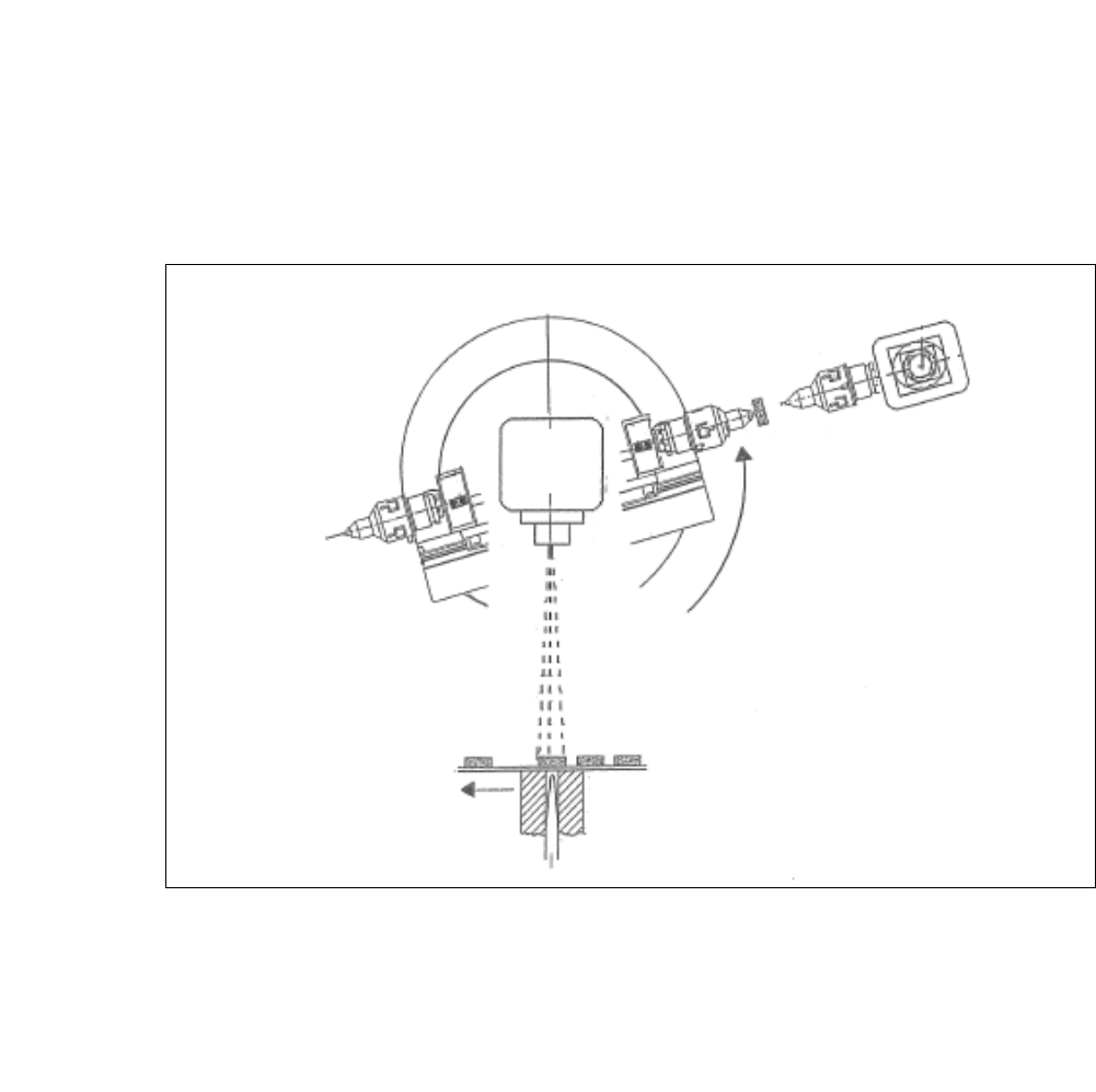
4.1.5.1 Flip Chip Segment 1 (Nozzle)
4
Fig. 4.1 - 6 Flip Chip Segment 1 (Nozzle)
(1) The wafer X-Y travels to the next chip
(2) The flip chip rotary unit segment 1 turns to the handover position "Die Attach".
During the rotation (from the camera "free Position") the picture recognition of the next chip
is carried out. 4
Wafer
Camera
4 SIPLACE Wafer System (SWS) User Manual SIPLACE CA-Series
4.1 Functions From software version SC.708.0 Edition 12/2014
208
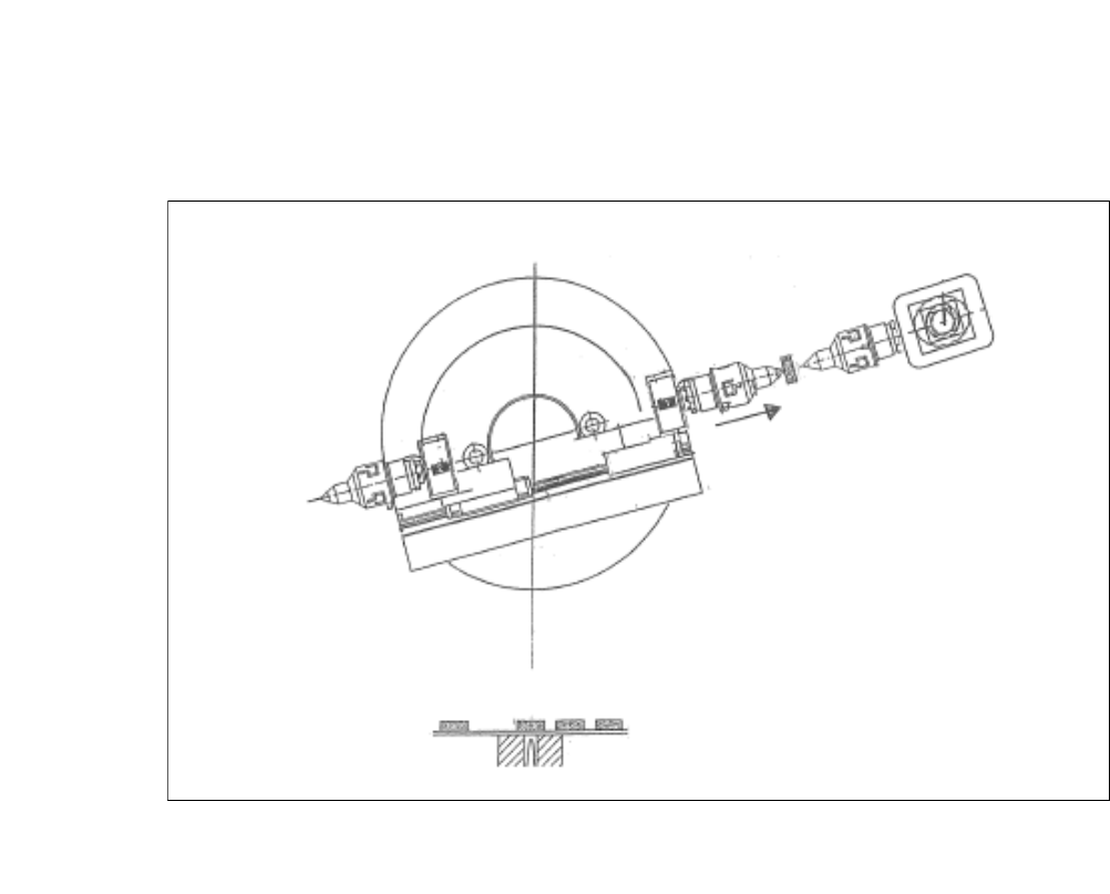
4.1.5.2 Flip Chip Segment 1 (Z Direction)
4
Fig. 4.1 - 7 Flip Chip Segment 1 (Z Direction)
(1) The x-axis of the flip chip swivel segment 1 is moved to the transfer position.
User Manual SIPLACE CA-Series 4 SIPLACE Wafer System (SWS)
From software version SC.708.0 Edition 12/2014 4.1 Functions
209
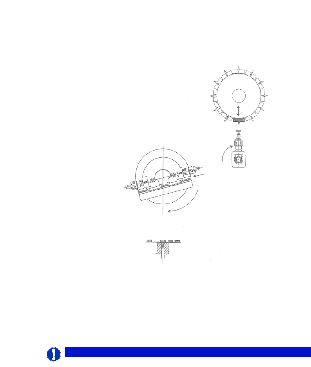
4.1.5.3 Die Attach - Transfer Position
4
Fig. 4.1 - 8 Die Attach - Transfer Position
(1) The die attach rotates to the transfer position.
(2) The SIPLACE head picks the chip up from the die attach segment and rotates to the next star
position.
(3) At the same time the X axis retracts the segment no. 1 back into the home position.
(4) The flip chip unit - segment no. 1 rotates to the transfer position and picks up the next chip.
4
PLEASE NOTE
While using the die attach unit only the segment no.1 of the flip chip unit is active.