00197498-03_UM_SiplaceCA-Serie_EN.pdf - 第21页
User manual SIPLACE CA-Series 1 Introduction From software version SC.708.0 Edition 12/2014 EN -DRAFT 1.2 Machine Description 21 1.1.1.1 Overview of Placement Head Configuration 1 The performance dat a can be found in se…
1 Introduction User manual SIPLACE CA-Series
1.1 Machine Overview From software version SC.708.0 Edition 12/2014 EN -DRAFT
20
1.1 Machine Overview
1.1.1 SIPLACE CA4
1
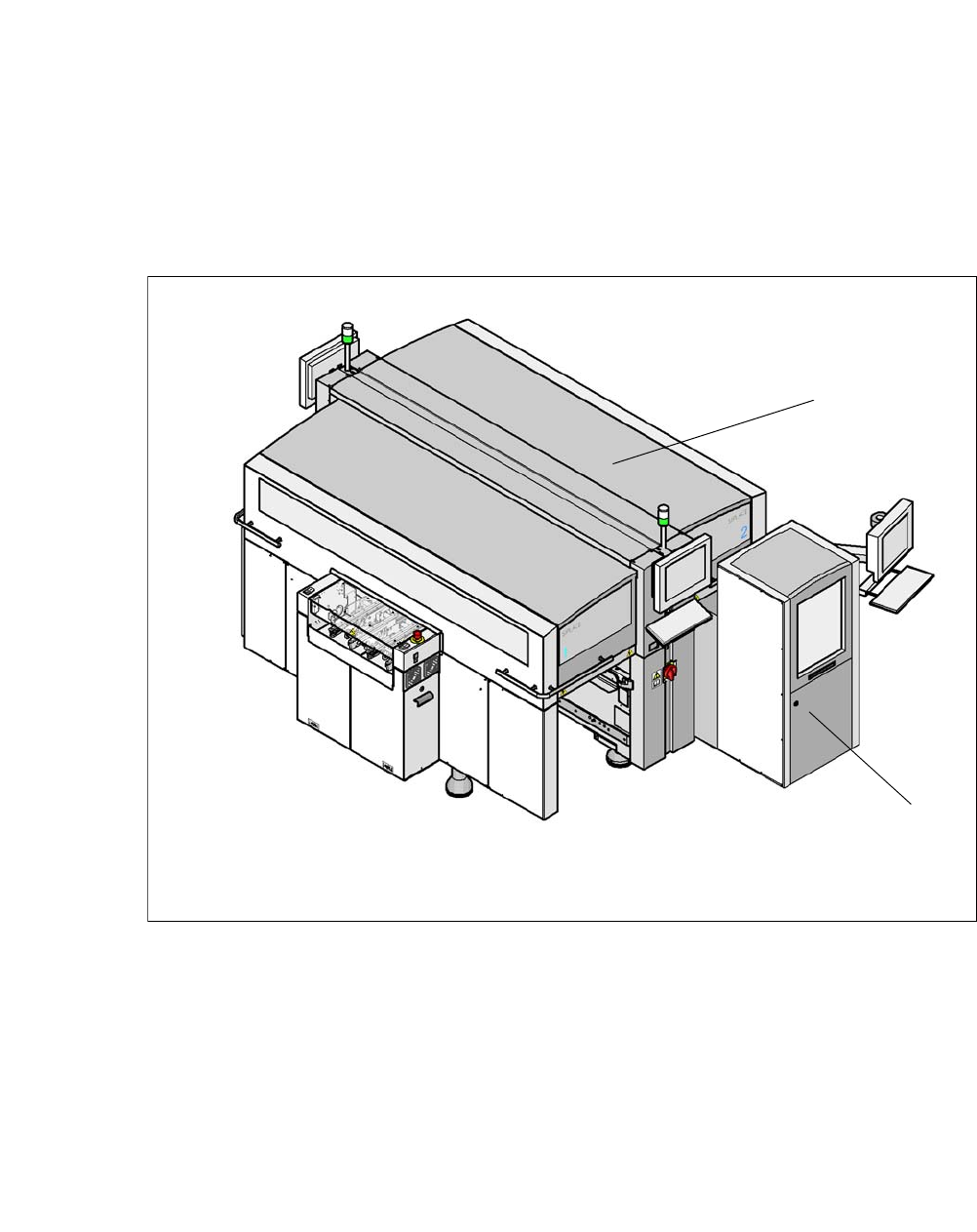
Fig. 1.1 - 1 SIPLACE CA4 placement machine with SIPLACE Wafer System (SWS)
(1) SIPLACE CA4
(2) SIPLACE Wafer System (SWS)
The CA4 placement machine has four gantries, two for each placement area (PA). All the gantry
axes are driven by linear motors. The gantry axes can be positioned quickly and accurately in the
X and Y directions. The gantry arms are lightweight constructions made from a highly rigid carbon
fiber composite material.
The placement machine has at least one SIPLACE Wafer System (SWS) at one of the four loca-
tions, so that dies can be placed from wafers.
1
2
User manual SIPLACE CA-Series 1 Introduction
From software version SC.708.0 Edition 12/2014 EN -DRAFT 1.2 Machine Description
21
1.1.1.1 Overview of Placement Head Configuration
1
The performance data can be found in section 3.1, page 121.
1.2 Machine Description
The SIPLACE CA placement systems impress with high configuration flexibility, top placement
performance and maximum precision. The SIPLACE CA can place bare dies directly from the wa-
fer, by using the flip chip or die attach process, and can also place the entire SMD spectrum cov-
ered by the SIPLACE X machines.
Two placement methods are used on the placement machines:
– The Collect&Place method for high-speed placement of standard components
– The Pick&Place method for fast placement of special components in the fine-pitch and super
fine-pitch range
The SIPLACE CA is based on the well-proven hardware and software of the SIPLACE X machine.
Various modifications to the hardware and software enable the SIPLACE CA to operate with an
innovative new design: the SIPLACE Wafer System (SWS), which uses the same user interface
for both SIPLACE Pro and the station software. The placement machine has at least one SI-
PLACE Wafer System (SWS) at one of the four locations, so that dies can be placed from wafers.
The Siplace CA can also be operated without the SWS, in the same way as an X-Series machine.
This makes the components (dies) directly available to the placement head, in so-called wafers.
The gantries that are driven by linear motors can be positioned fast and precisely in X and Y di-
rection. Each gantry has one placement head.
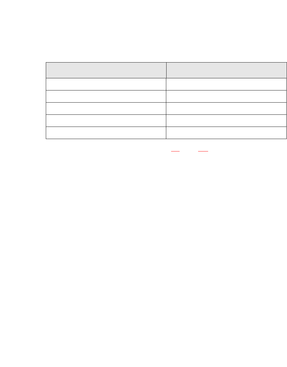
Placement area 1 Placement area 2
C&P20 M / C&P20 M C&P20 M / C&P20 M
C&P20 M / C&P20 M CPP / CPP
CPP / CPP CPP / CPP
C&P20 M / C&P20 M CPP / TH
CPP / CPP CPP / TH

1 Introduction User manual SIPLACE CA-Series
1.2 Machine Description From software version SC.708.0 Edition 12/2014 EN -DRAFT
22
The moving head picks the components up from the waiting SWS and places them on the waiting
printed circuit board. This proven SIPLACE principle has many advantages:
– No downtime due to refilling or splicing
– Safe pick up of even the smallest components
– No shifting of the components on the circuit board
– Minimized travel range
High flexibility, economic efficiency and reliable setups are the guarantee for the high level of pro-
ductivity in the SIPLACE CA placement systems. Minimum down times increase utilization and
thus help to increase productivity. Even small 03015 components can be processed with the SI-
PLACE CA-Series.
1.2.1 Description of the SIPLACE Wafer System (SWS)
1.2.1.1 Description and Function
Up to four SIPLACE Wafer Systems (SWS) can be used at the SIPLACE CA placement machines.
The SWS provides the placement head with components directly from the wafer. The SWS there-
fore extends the component spectrum of the established SIPLACE X machines, by enabling
placement of bare dies from wafers.
The wafer is fed in fully automatically, by the wafer magazine and the components can then be
processed using the customary placement procedure.
Flip chip process - function
The wafers are transported fully automatically from the wafer magazine to the wafer table. This
then positions the die concerned over the ejection system, which releases the die from the wafer
foil. After this release procedure, the flip unit nozzle takes the die, rotates it by 180° and makes it
available to the placement head for pickup.
The process spectrum is supplemented by the following options:
– Die attach unit:
The die attach unit takes the die from the flip unit nozzle and turns it, so that it has the same
top-bottom orientation on the board as it had on the wafer.
– Linear Dipping Unit
The Linear Dipping Unit distributes precise layers of flux for the flip chip process. After taking
over from the flip unit the placement head dips the die in to the flux layer.