00197498-03_UM_SiplaceCA-Serie_EN.pdf - 第212页
4 SIPLACE Wafer System (SWS) User Manual SIPLACE CA- Series 4.1 Functions From software version SC.708.0 Edition 12/2014 212 4 Fig. 4.1 - 1 1 Positions flip head/die attach segment The transfer position of the flip head,…
User Manual SIPLACE CA-Series 4 SIPLACE Wafer System (SWS)
From software version SC.708.0 Edition 12/2014 4.1 Functions
211
4
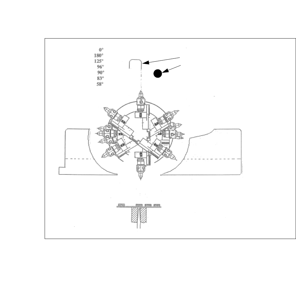
Fig. 4.1 - 10 Initialization of flip rotation axis
(1) Mechanical Stop
(2) Home sensor
The home sensor is used to initialize the flip rotation axis. During the initialization the rotation axis
travels slowly until the home sensor triggers. Afterwards the first zero pulse is looked up in an area
of 0-30° of the rotation axis. Through that the zero position of the flip rotation axis is defined.
Reject bin
Segment no. 2
Reject bin
Segment no. 1
1. Mechanical Stop
2. Home sensor
4 SIPLACE Wafer System (SWS) User Manual SIPLACE CA-Series
4.1 Functions From software version SC.708.0 Edition 12/2014
212
4
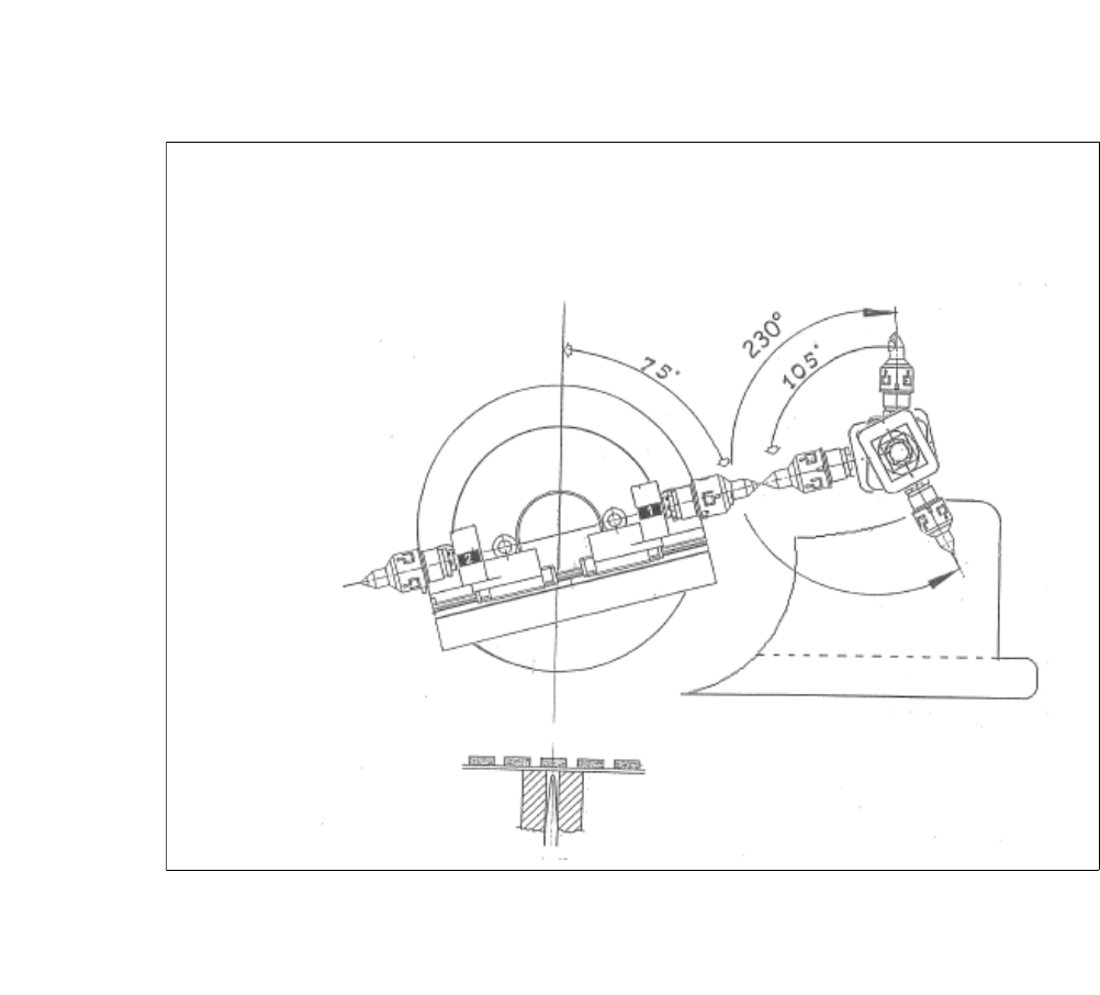
Fig. 4.1 - 11 Positions flip head/die attach segment
The transfer position of the flip head, the pick up and discharge position, as well as the transfer
position of the die attach segment to the placement head.
User Manual SIPLACE CA-Series 4 SIPLACE Wafer System (SWS)
From software version SC.708.0 Edition 12/2014 4.2 Overview of the Modules
213
4.2 Overview of the Modules
4
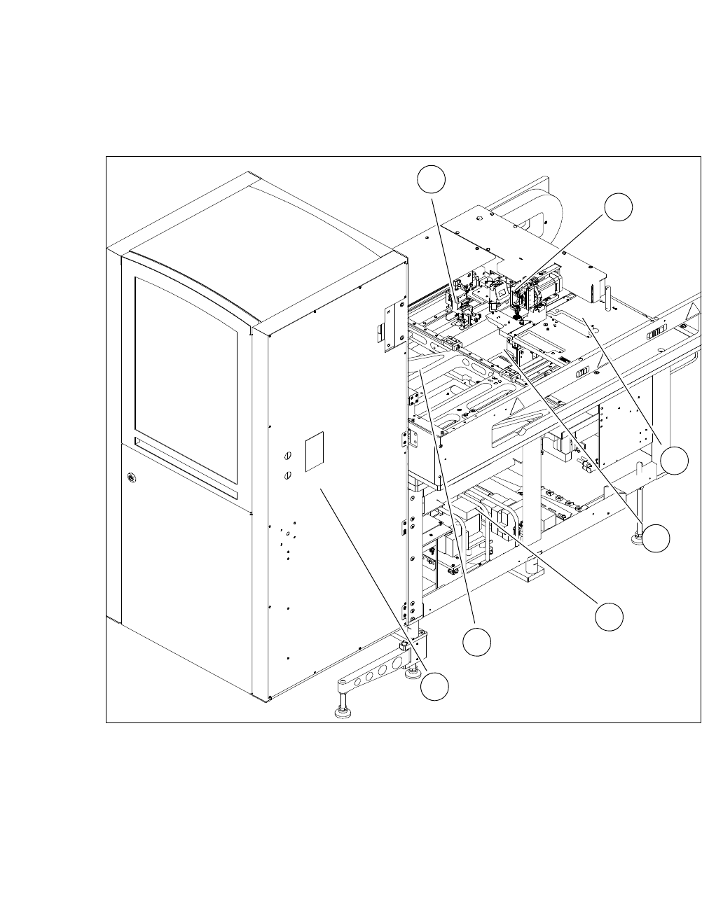
Fig. 4.2 - 1 Overview of the SWS
4
(1) Gripper (2) Flip Unit
(3) Installation location for options (die attach
unit or linear dipping unit)
(4) Die Ejector
(5) Supply Unit (6) X unit
(7) Magazine lift
1
2
3
4
5
6
7