00197498-03_UM_SiplaceCA-Serie_EN.pdf - 第222页
4 SIPLACE Wafer System (SWS) User Manual SIPLACE CA- Series 4.3 Description of the SWS Modules From software version SC.708.0 Edition 12/2014 222 4 Fig. 4.3 - 6 Wafer support with wafer inserted (example for 12") (1…
User Manual SIPLACE CA-Series 4 SIPLACE Wafer System (SWS)
From software version SC.708.0 Edition 12/2014 4.3 Description of the SWS Modules
221
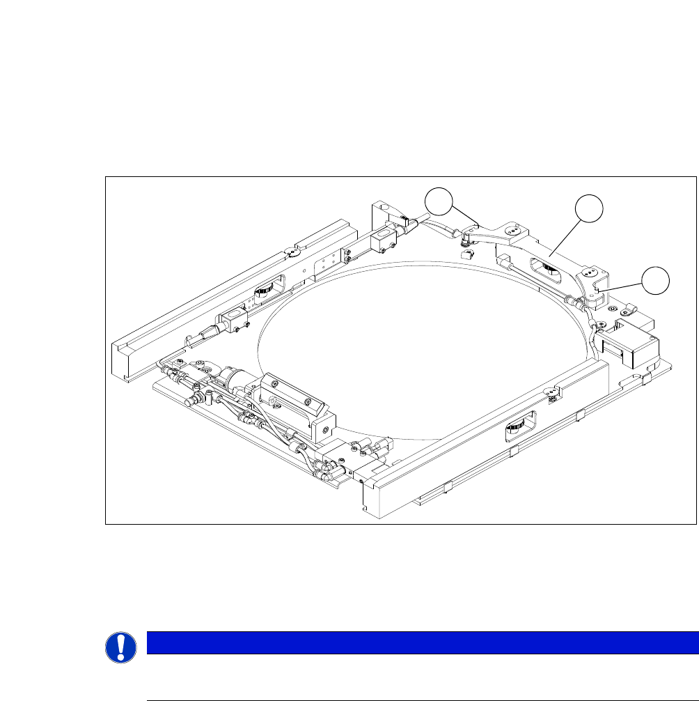
4.3.4.1 Wafer support
The wafer support is fitted to the X-Y unit and is therefore part of the wafer table. The wafers are
fixed to this for the ejection procedure.
4
Fig. 4.3 - 5 Wafer support without wafer inserted (example for 12")
(1) Pin for the locking and position recognition of 12" wafers
(2) Wafer locking bar
4
PLEASE NOTE
To process 8" wafers, you need to change the wafer support.
Frames for 6" wafers can be used with the relevant adapters.
1
2
1
4 SIPLACE Wafer System (SWS) User Manual SIPLACE CA-Series
4.3 Description of the SWS Modules From software version SC.708.0 Edition 12/2014
222
4
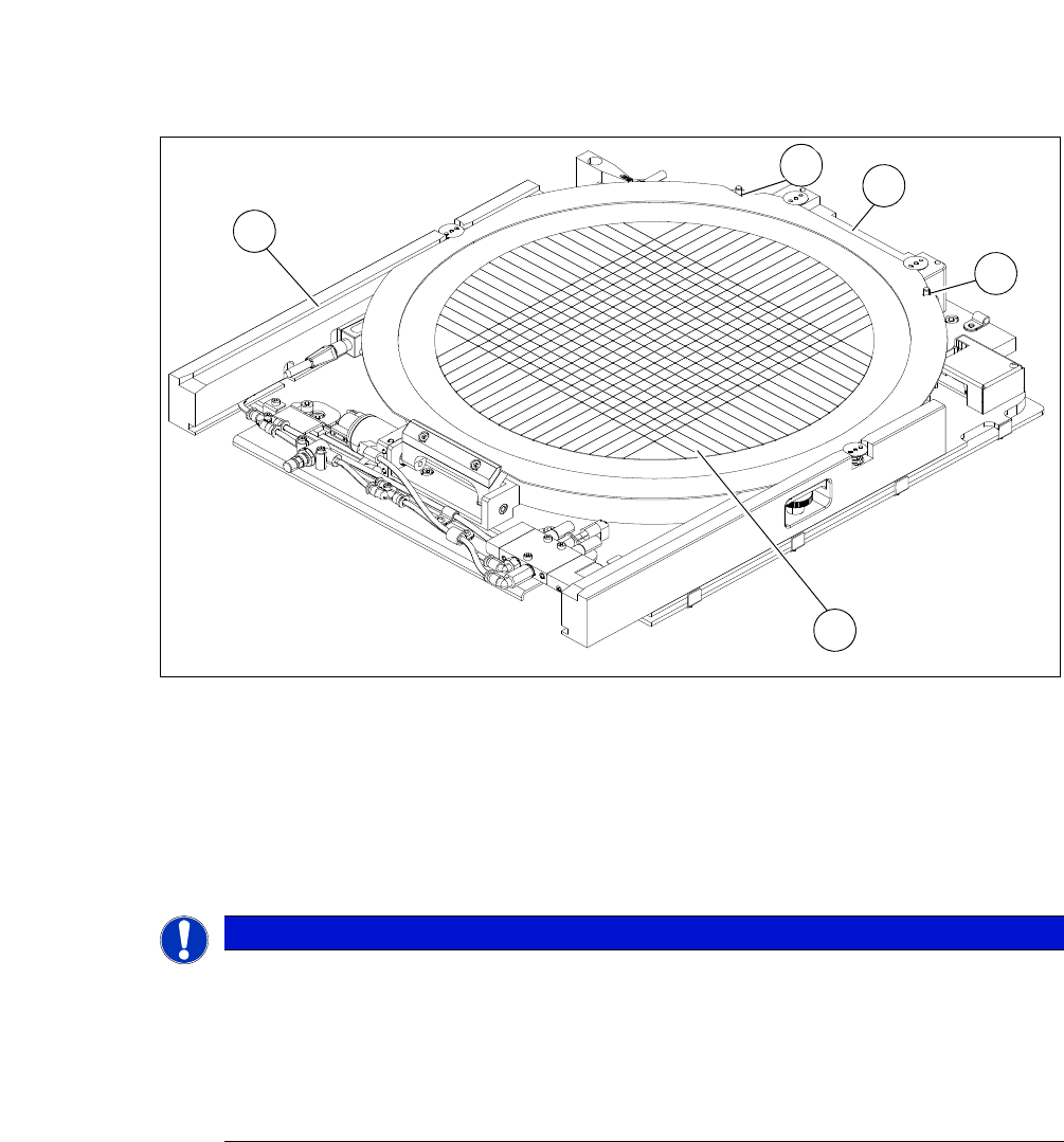
Fig. 4.3 - 6 Wafer support with wafer inserted (example for 12")
(1) Recess for the defined positioning on the pins of the locking bar
(2) Wafer locking bar
(3) Wafer
(4) Rail
4
4
PLEASE NOTE
Problems recognizing frames during clamping
If the wafer locking bar (2) has been incorrectly attached, the frame will not be recognized
correctly during clamping.
When using 8" wafer supports, make sure that the wafer locking bar (2) is attached in
a manner that allows the pins of the locking bar to engage with the recess on the wa-
fer frame.
3
1
4
2
1
User Manual SIPLACE CA-Series 4 SIPLACE Wafer System (SWS)
From software version SC.708.0 Edition 12/2014 4.3 Description of the SWS Modules
223
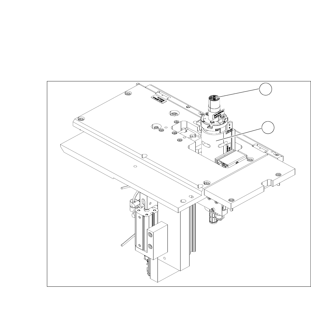
4.3.5 Die Ejector
According to the location (2 and 4 or 1 and 3) there are two different variants that only differ in their
mirror-inverted arrangement of the modules.
4
Fig. 4.3 - 7 Main die ejector modules
(1) Ejector tool
(2) Z axis
1
2