00197498-03_UM_SiplaceCA-Serie_EN.pdf - 第23页
User manual SIPLACE CA-Series 1 Introduction From software version SC.708.0 Edition 12/2014 EN -DRAFT 1.2 Machine Description 23 1.2.1.2 SWS Inst allation Options The SWS can be integrated into all 4 locations. 1 1.2.2 T…

1 Introduction User manual SIPLACE CA-Series
1.2 Machine Description From software version SC.708.0 Edition 12/2014 EN -DRAFT
22
The moving head picks the components up from the waiting SWS and places them on the waiting
printed circuit board. This proven SIPLACE principle has many advantages:
– No downtime due to refilling or splicing
– Safe pick up of even the smallest components
– No shifting of the components on the circuit board
– Minimized travel range
High flexibility, economic efficiency and reliable setups are the guarantee for the high level of pro-
ductivity in the SIPLACE CA placement systems. Minimum down times increase utilization and
thus help to increase productivity. Even small 03015 components can be processed with the SI-
PLACE CA-Series.
1.2.1 Description of the SIPLACE Wafer System (SWS)
1.2.1.1 Description and Function
Up to four SIPLACE Wafer Systems (SWS) can be used at the SIPLACE CA placement machines.
The SWS provides the placement head with components directly from the wafer. The SWS there-
fore extends the component spectrum of the established SIPLACE X machines, by enabling
placement of bare dies from wafers.
The wafer is fed in fully automatically, by the wafer magazine and the components can then be
processed using the customary placement procedure.
Flip chip process - function
The wafers are transported fully automatically from the wafer magazine to the wafer table. This
then positions the die concerned over the ejection system, which releases the die from the wafer
foil. After this release procedure, the flip unit nozzle takes the die, rotates it by 180° and makes it
available to the placement head for pickup.
The process spectrum is supplemented by the following options:
– Die attach unit:
The die attach unit takes the die from the flip unit nozzle and turns it, so that it has the same
top-bottom orientation on the board as it had on the wafer.
– Linear Dipping Unit
The Linear Dipping Unit distributes precise layers of flux for the flip chip process. After taking
over from the flip unit the placement head dips the die in to the flux layer.

User manual SIPLACE CA-Series 1 Introduction
From software version SC.708.0 Edition 12/2014 EN -DRAFT 1.2 Machine Description
23
1.2.1.2 SWS Installation Options
The SWS can be integrated into all 4 locations.
1
1.2.2 The SIPLACE Principle
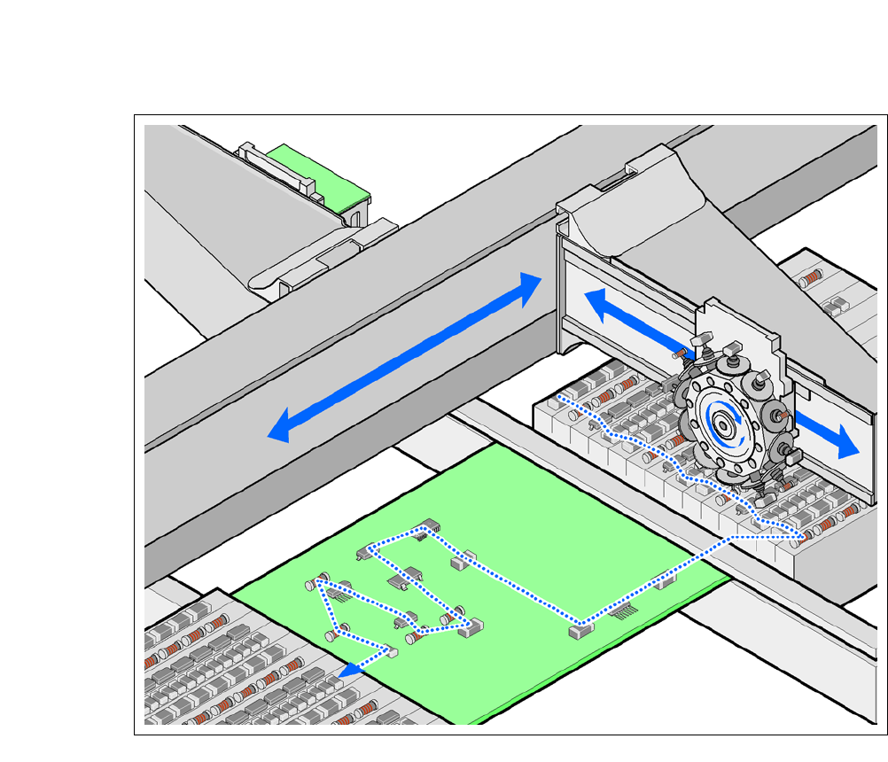
The SIPLACE Wafer Systems make bare dies available in fixed pickup positions, for pickup with
the die attach or flip chip methods. The other components are made available by the fixed feeders
on the component trolley and on the trays of the Matrix Tray Changer. The placement heads pick
the bare dies and components up and place these on the waiting printed circuit boards.
The CA-Series placement machines have two placement areas:
– As in the case of SIPLACE X machines, up to two boards can be processed simultaneously
for single conveyors and up to four boards can be processed at the same time for dual con-
veyors.
The principle of the "stationary component supply" and "stationary PCB", which has proved highly
suitable for all SIPLACE placement machines, has a number of significant advantages:
– Refilling components or splicing on tapes does not cause downtime.
– The vibration-free feeding in of components enables reliable pickup of even the smallest com-
ponents (e.g. 03015) and bare dies.
– The PCB, which does not move during the placement process, prevents the components slip-
ping.
– The combination of placement heads with nozzle changers always guarantees an optimum
nozzle configuration for every placement process, thus minimizing traversing paths and opti-
mizing the placement sequence.
High flexibility, economic efficiency and reliable setups are the guarantee for the high level of pro-
ductivity in the SIPLACE CA-Series machines. Minimum down times increase utilization and thus
help to increase productivity.
Since this new concept combines at least two production lines to form a single line (SMD and bare
die placement), the investment costs and cost of ownership can be reduced significantly.
PLEASE NOTE
SWS types
There are two different variants of the SWS.
– The first type can be fitted at locations 2 and 4.
– The second type can be fitted at locations 1 and 3.
1 Introduction User manual SIPLACE CA-Series
1.2 Machine Description From software version SC.708.0 Edition 12/2014 EN -DRAFT
24
1
Fig. 1.2 - 1 Placement principle according to the Collect&Place procedure