00197498-03_UM_SiplaceCA-Serie_EN.pdf - 第230页
4 SIPLACE Wafer System (SWS) User Manual SIPLACE CA- Series 4.3 Description of the SWS Modules From software version SC.708.0 Edition 12/2014 230 4 Fig. 4.3 - 13 Main gripper modules (location 1,3) 4 (1) Gripper (2) T oo…
User Manual SIPLACE CA-Series 4 SIPLACE Wafer System (SWS)
From software version SC.708.0 Edition 12/2014 4.3 Description of the SWS Modules
229
4.3.7.2 Wafer changer
According to the location (2 and 4 or 1 and 3) there are two different versions of the wafer changer.
4
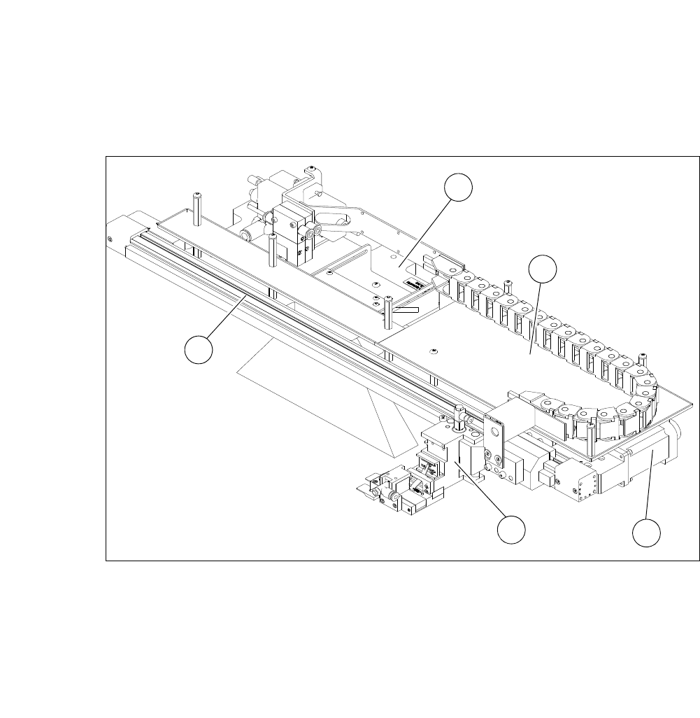
Fig. 4.3 - 12 Main gripper modules (location 2,4)
4
(1) Gripper (2) Toothed belt axis
(3) Installation location for barcode scanner
(optional)
(4) AD-MOT board below the cover
(5) Motor with coupling
1
4
5
3
2
4 SIPLACE Wafer System (SWS) User Manual SIPLACE CA-Series
4.3 Description of the SWS Modules From software version SC.708.0 Edition 12/2014
230
4
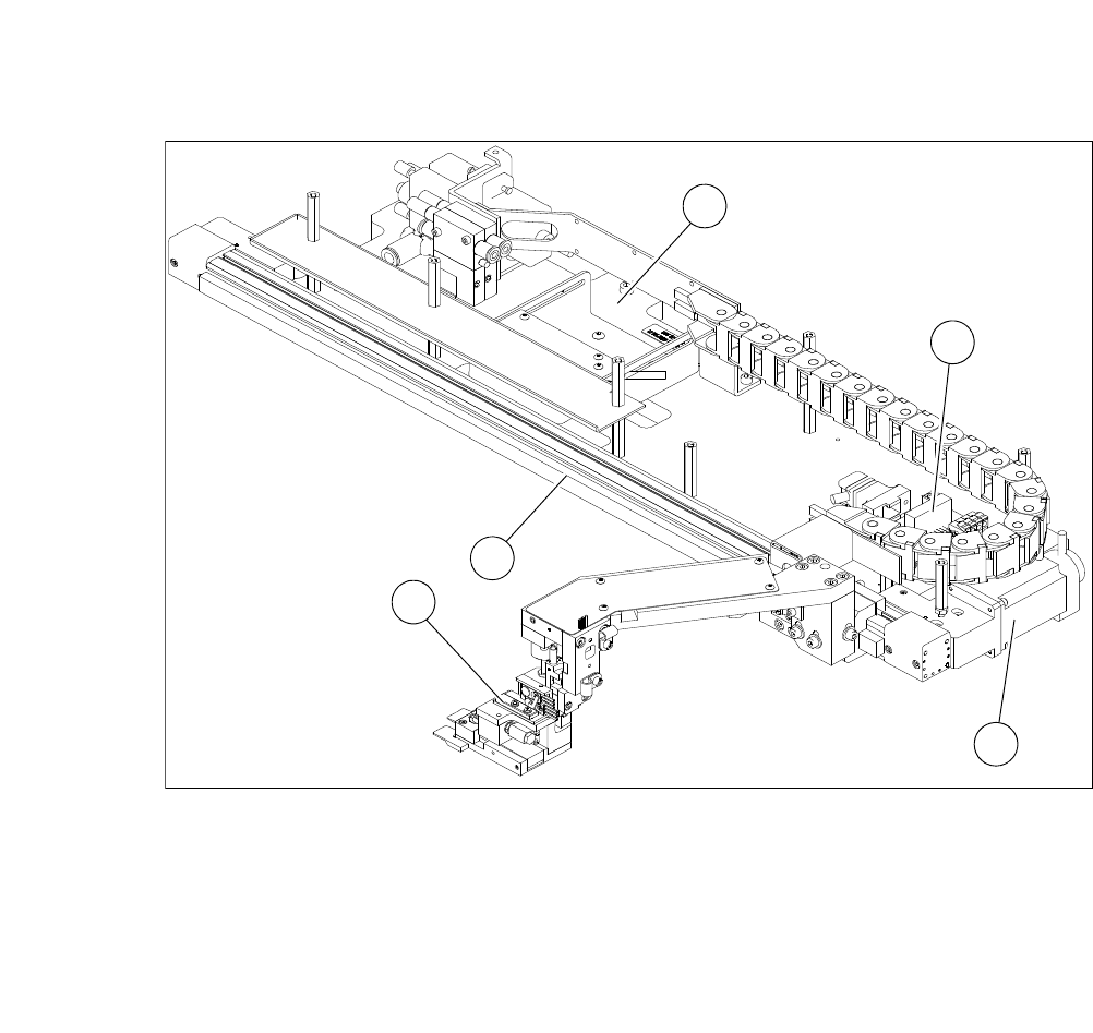
Fig. 4.3 - 13 Main gripper modules (location 1,3)
4
(1) Gripper (2) Toothed belt axis
(3) Insertion location for barcode scanner
(optional)
(4) AD-MOT board
(5) Motor with coupling
1
2
4
5
3
User Manual SIPLACE CA-Series 4 SIPLACE Wafer System (SWS)
From software version SC.708.0 Edition 12/2014 4.4 Optional Components
231
4.4 Optional Components
4.4.1 Linear Dipping Unit (LDU)
4
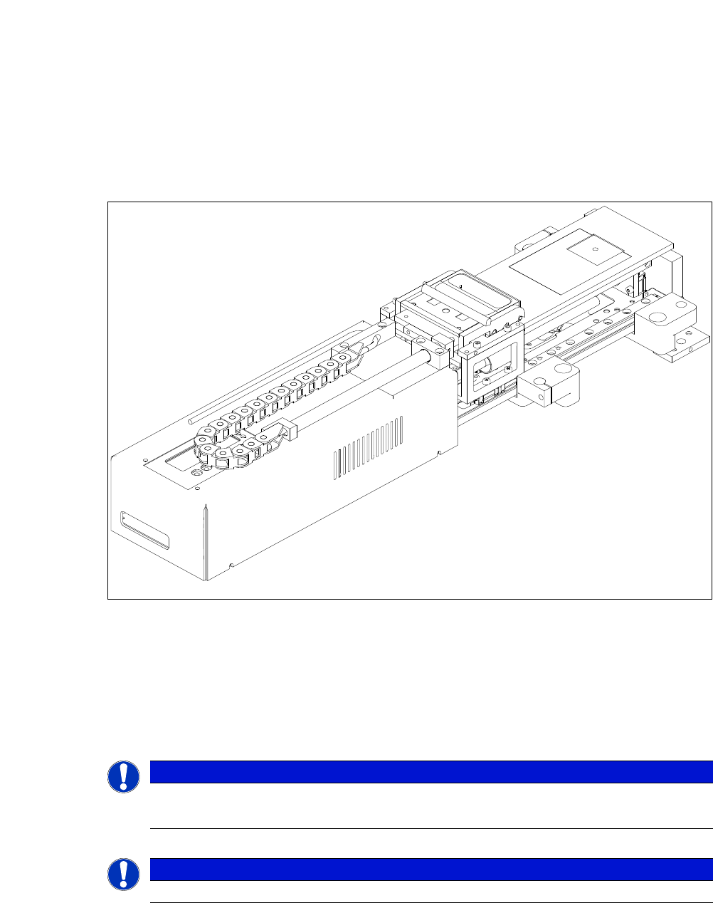
Fig. 4.4 - 1 Linear Dipping Unit (LDU)
The Linear Dipping Unit (LDU) is often needed, to apply flux to the die during the flip chip process.
This is required to ensure a reliable reflow process.
The LDU is able to apply highly accurate layers of flux. This flux is made available in a so-called
cavity. The depth of the cavity determines the thickness of the flux layer.
4
4
PLEASE NOTE
The LDU must be provided for all types of suitable flip chip fluxes.
Only use epoxide and solder pastes after internal factory tests have been performed.
PLEASE NOTE
Do not use the LDU together with the die attach unit.