00197498-03_UM_SiplaceCA-Serie_EN.pdf - 第234页
4 SIPLACE Wafer System (SWS) User Manual SIPLACE CA- Series 4.4 Optional Components From software version SC.708.0 Edition 12/2014 234 4 Fig. 4.4 - 3 Barcode scanner - installation example in the wafer change r (1) Barco…

User Manual SIPLACE CA-Series 4 SIPLACE Wafer System (SWS)
From software version SC.708.0 Edition 12/2014 4.4 Optional Components
233
4.4.3 Small Die Kit
The small die kit is used if you need to process dies which are smaller than 1 mm. This kit is avail-
able on request as an option and consists of the following parts:
– A high-resolution camera system
– A small die ejector tool
– A component sensor
4.4.4 Wafer Map System
Wafer mapping is increasingly becoming a standard in die placement processes. The wafer map
assigns a function class to each die on the wafer.
The function class could simply be "good" or "bad". However, up to 255 classes can be assigned
to describe the die properties in detail.
Firstly, the SWS needs to identify the wafer. Normally, this involves reading in the barcode on the
wafer frame. This wafer ID is then used to select the required wafer file on the wafer map server.
In a second step, the abstract die ID from the wafer map file (column/row) is set in relation to the
real position of the die on the wafer. This position can be calculated by identifying special refer-
ence dies on the wafer and by determining the wafer center.
4
The wafer map function is primarily a software option. This includes a server system for the wafer
map files, with a conversion from customer-specific wafer map standard to the SWS standard.
4.4.5 Barcode Scanner
The barcode scanner on the SWS reads the barcode on the wafer frame.
PLEASE NOTE
Position calculation
The calculation of positions with the help of the wafer edge recognition function only
works reliably for dies which are 3 mm or larger.
4 SIPLACE Wafer System (SWS) User Manual SIPLACE CA-Series
4.4 Optional Components From software version SC.708.0 Edition 12/2014
234
4
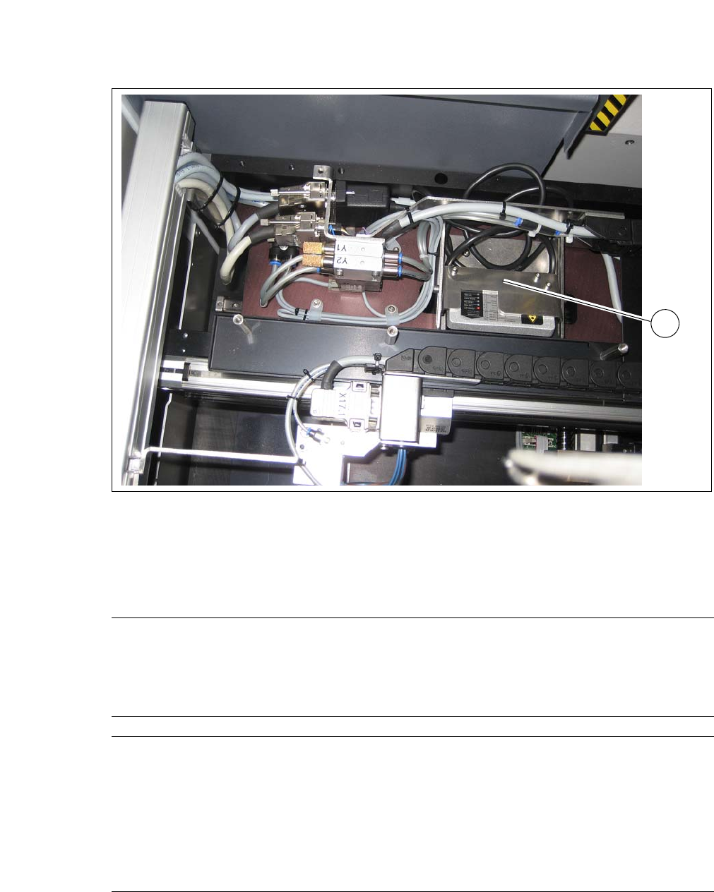
Fig. 4.4 - 3 Barcode scanner - installation example in the wafer changer
(1) Barcode Scanner
4.4.5.1 Technical Data
1
Board size
Length 50 mm to 610 mm
Width 50 mm to 508 mm
Thickness 0.3 mm to 4.5 mm
Curvature Up to 0.5 mm
Board types PCB, FR4, BGA, Boat, Leadframe
SIPLACE Wafer System
Placement method Flip chip, die attach
Die size 0.8 mm x 0.8mm up to 12 x12 mm
(larger dies on request)
Die thickness 0.05 mm to 4 mm
Wafer size Up to 12"
Frame size up to 15"
Wafer cassette max. 25 slots
User Manual SIPLACE CA-Series 4 SIPLACE Wafer System (SWS)
From software version SC.708.0 Edition 12/2014 4.5 SIPLACE SWS Wafer Stretcher
235
4.5 SIPLACE SWS Wafer Stretcher
The SIPLACE Wafer System (SWS) can be configured with the SIPLACE SWS Wafer Stretcher
option for two different wafer supports (8" or 12").
The SIPLACE SWS Wafer Stretcher consists of the following main assemblies.
– Stretcher
The stretcher stretches the wafer foil to increase the distances of the dies on it. 4
–Heater
The heater consists of a heating element and a fan. The fan blows heated air on to the wafer
foil. This reduces the sag of the wafer foil (less than 9 mm), so that the wafer can be trans-
ported back into the magazine. 4
4
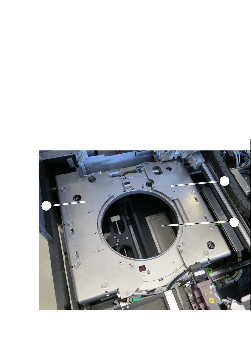
Fig. 4.5 - 1 Wafer support with SIPLACE SWS Wafer Stretcher
(1) Stretcher frame with wafer support
(2) Heater fan
2
1
1