00197498-03_UM_SiplaceCA-Serie_EN.pdf - 第260页
5 Setting up and Commissioning User Manual SIPLACE CA-Series 5.2 Delivery Configuration and Transportation of Placement Ma chine From software version SC.708.0 Edition 12/2014 EN -DRAFT 260 5.2.3 T ransporting the Placem…
User Manual SIPLACE CA-Series 5 Setting up and Commissioning
From software version SC.708.0 Edition 12/2014 EN -DRAFT 5.2 Delivery Configuration and Transportation of Placement Machine
259
5
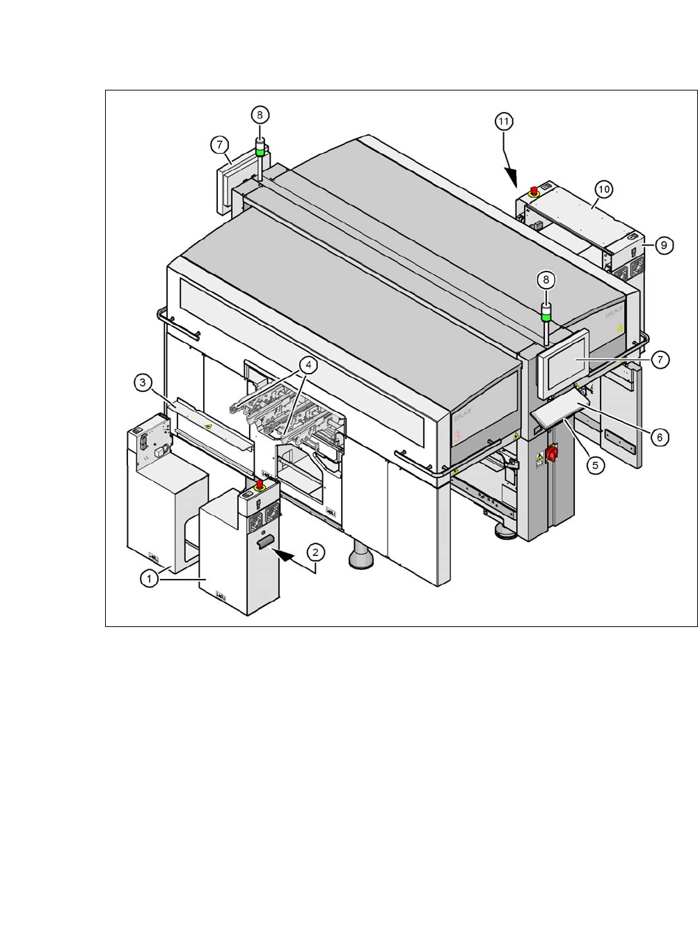
Fig. 5.2 - 2 Delivery configuration of placement machine
(1) Extension kit on the PCB output side - removed and dismantled for delivery
(2) Axis unit on the PCB output side - CA4: Gantries 2 and 3
(3) Transportation cover
(4) Output conveyor
(5) Keyboard supporting plate
(6) Keyboard
(7) Monitor
(8) Main fault indicator
(9) Computer unit on the PCB input side
(10) Extension kit at the PCB input side - can be disassembled if necessary
(11) Axis unit on the PCB output side - CA4: Gantries 1 and 4
5 Setting up and Commissioning User Manual SIPLACE CA-Series
5.2 Delivery Configuration and Transportation of Placement Machine From software version SC.708.0 Edition 12/2014 EN -DRAFT
260
5.2.3 Transporting the Placement Machine in a Crate
5.2.3.1 Services
One of the services provided by ASM Assembly Systems GmbH & Co.KG is the complete inte-
gration of CA-Series placement machines into your production line. With our extensive expertise
and by using the right tools and equipment, we can ensure that the installation process runs
smoothly and efficiently. However, this will require you to clarify the infrastructure aspects in ad-
vance and make any necessary changes at your production facility.
Please note that the safest way to transport the placement machine is always in the transport crate
- or at the very least on the pallet. This will prevent serious damage to the placement machine
caused by the feet colliding with obstacles, for example.
5.2.3.2 Safety instructions
5
5
5
5.2.3.3 Means of Transport
To transport the placement machine on the wooden pallet or in the transport crate, use a fork-lift
truck with the following specifications:
Fork length: Min. 1,800 mm
Carrying power: Min. 6,000 kg
Clear width between forks: Min. 350 mm 5
WARNING
Observe the applicable accident prevention regulations!
The applicable accident prevention regulations concerning the transportation of
heavy goods must be followed.
WARNING
Risk of tilting!
This risk occurs if the required specifications for the fork-lift truck are not observed (sec-
tion 5.2.3.3
)!
Only use the specified fork-lift for transportation.
WARNING
DANGER OF CRUSHING!
Risk of crushing feet when transporting the machine.
Wear special protective shoes.
User Manual SIPLACE CA-Series 5 Setting up and Commissioning
From software version SC.708.0 Edition 12/2014 EN -DRAFT 5.2 Delivery Configuration and Transportation of Placement Machine
261
5.2.3.4 Fork-lift Attachment Points on the Transport Crate or Pallet
Position the fork-lift truck only at the points marked (A). in fig. 5.2 - 1. We recommend that you
keep the crate or the pallet with packaging for later use.
5
5
5.2.4 Transporting the Placement Machine Without a Crate or Pallet
5.2.4.1 Safety instructions
5
5
5
5
WARNING
Damage to the machine!
Risk of damaging the machine if it is transported without crate or pallet.
Observe the information in the next section.
WARNING
Observe the applicable accident prevention regulations!
The applicable accident prevention regulations concerning the transportation of
heavy goods must be followed.
WARNING
DANGER OF CRUSHING!
Risk of crushing feet when transporting the machine.
Wear special protective shoes.
WARNING
Damage to the machine!
Risk of damaging the machine if it is transported without crate or pallet.
Read this section through completely before transporting the machine.
WARNING
Risk of damage!
The thread for the machine feet in the machine frame could be damaged by being dragged
along the floor or from impact.
When you are transporting the machine, make sure that all the feet are clear of the
floor.