00197498-03_UM_SiplaceCA-Serie_EN.pdf - 第265页
User Manual SIPLACE CA-Series 5 Setting up and Commissioning From software version SC.708.0 Edition 12/20 14 EN -DRAFT 5.2 Delivery Configuration and Transportation of Placement Machine 265 5 5 5.2.4.4 Point s to be Obse…
5 Setting up and Commissioning User Manual SIPLACE CA-Series
5.2 Delivery Configuration and Transportation of Placement Machine From software version SC.708.0 Edition 12/2014 EN -DRAFT
264
Forks parallel to PCB conveyor 5
5
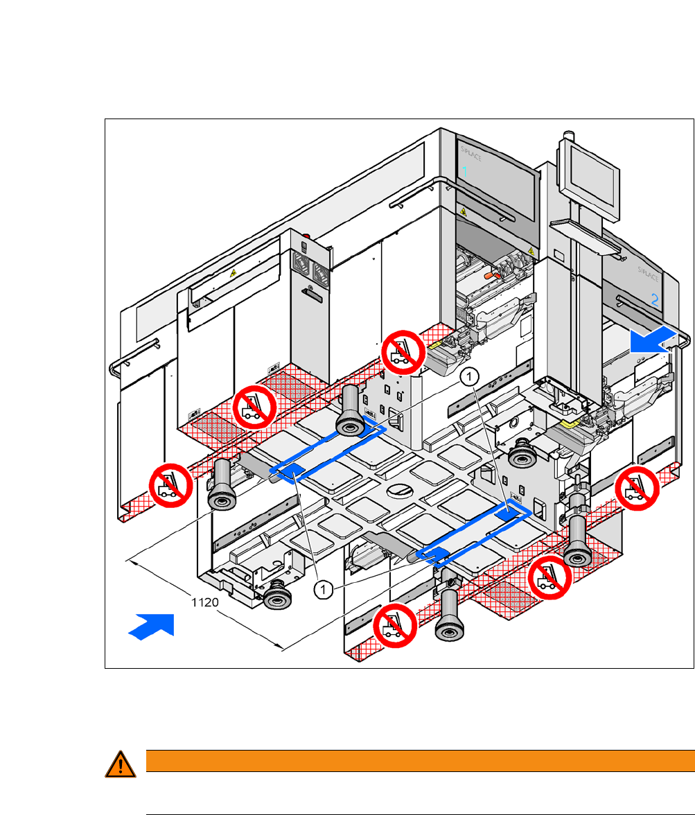
Fig. 5.2 - 4 Contact surfaces - Forks across the direction of PCB transport
(1) Contact surfaces for fork lift truck forks
5
WARNING
Please note the following points before you raise the machine, in order to avoid irre-
versible damage to the machine.
User Manual SIPLACE CA-Series 5 Setting up and Commissioning
From software version SC.708.0 Edition 12/2014 EN -DRAFT 5.2 Delivery Configuration and Transportation of Placement Machine
265
5
5
5.2.4.4 Points to be Observed While Transporting the Machine
5
WARNING
Risk of damage due to excessive fork spacing!
The distance between the forks must be between 800 and 900 mm. The attachment points
for the fork-lift truck can be seen in fig. 5.2 - 4
. The outer distance between the contact
surfaces is 1,120 mm.
Increased fork spacing, which means that the machine is raised at points outside its con-
tact surface, could lead to deformation of the machine frame and cause damage to cables
and lines.
The forks may only be opened to a degree which ensures that they are still within the
contact area of the machine underside (for contact surfaces see fig. 5.2 - 3
).
WARNING
Risk of damage due to one-sided loading!
One-sided loading of the machine feet e.g. from tilting the machine, could lead to defor-
mation of the machine feet.
Make sure that the forks are evenly loaded when you lift the machine.
Use a firm support layer between the forks and the machine.
Enlist the help of a second person to watch while you lift the machine and make sure
that the machine does not tip over to one side.
WARNING
Risk of damage!
The thread for the machine feet in the machine frame could be damaged by being
dragged along the floor or from impact.
When you are transporting the machine, make sure that all the feet are clear of the
floor.
5 Setting up and Commissioning User Manual SIPLACE CA-Series
5.3 Delivery Configuration and Transportation of SWS From software version SC.708.0 Edition 12/2014 EN -DRAFT
266
5.3 Delivery Configuration and Transportation of SWS
5.3.1 Shipping Packaging
Within Europe the SWS is transported on a wooden pallet and is wrapped in plastic foil. Outside
Europe, the machine is supplied in a wooden crate mounted on a stable wooden pallet.
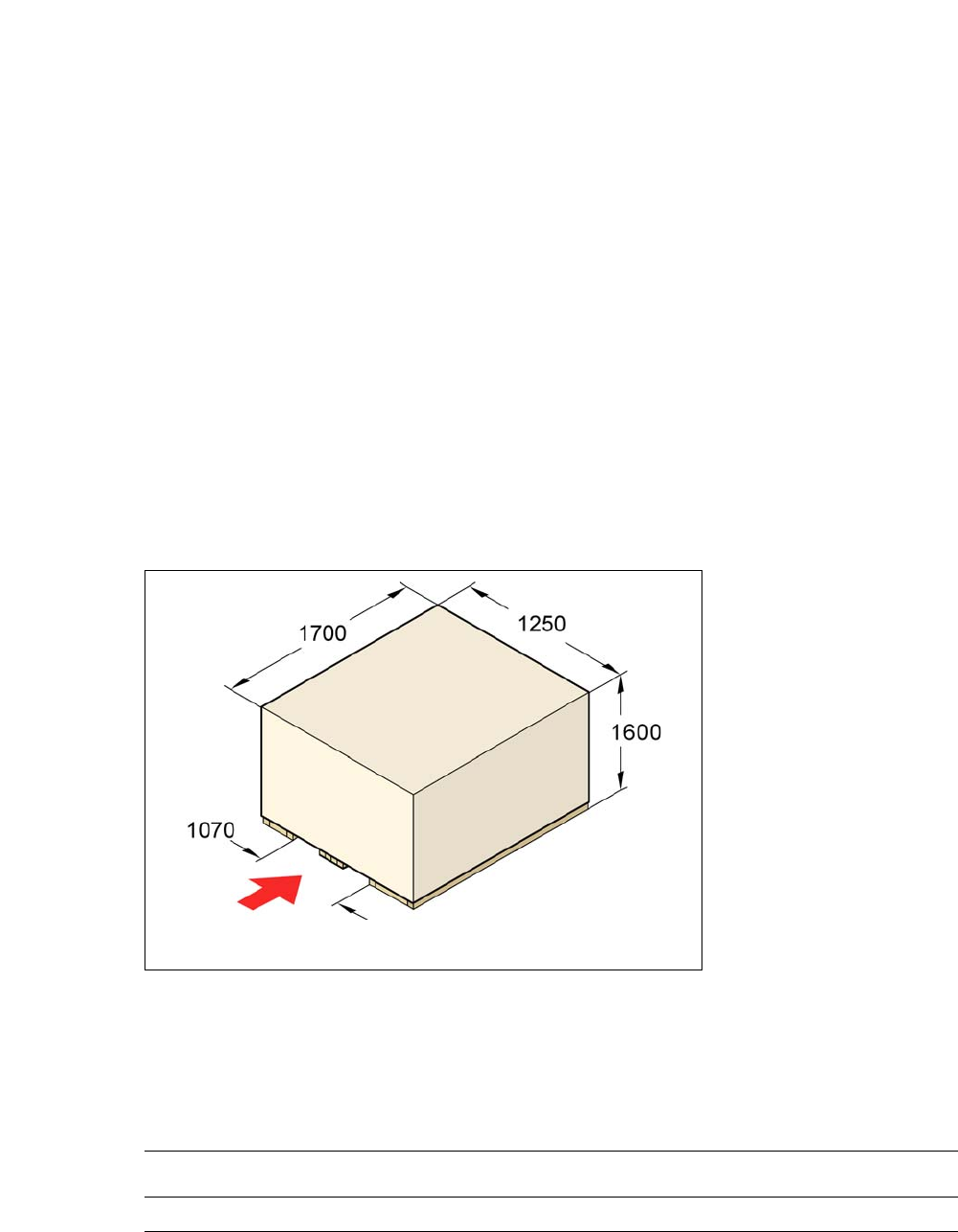
5.3.1.1 Dimensions of Transportation Packaging
The dimension of the wooden transport crate are as follows:
Length 1700 mm
Width 1250 mm
Height 1600 mm
5
5
Fig. 5.3 - 1 Transport crate SWS - dimensions in millimeters
5.3.1.2 Weight of Machine When Ready For Dispatch
The following table contains the weights of the machines prepared for dispatch, including packag-
ing.
5
fork-lift attachment
point
Machine Dispatch within Europe Dispatch overseas
SWS 390 kg 473 kg