00197498-03_UM_SiplaceCA-Serie_EN.pdf - 第270页
5 Setting up and Commissioning User Manual SIPLACE CA-Series 5.4 Infrastructure at the Installation Location From software version SC.708.0 Edition 12/2014 EN -DRAFT 270 5.4 Infrastructure at the Inst allation Location 5…
User Manual SIPLACE CA-Series 5 Setting up and Commissioning
From software version SC.708.0 Edition 12/2014 EN -DRAFT 5.3 Delivery Configuration and Transportation of SWS
269
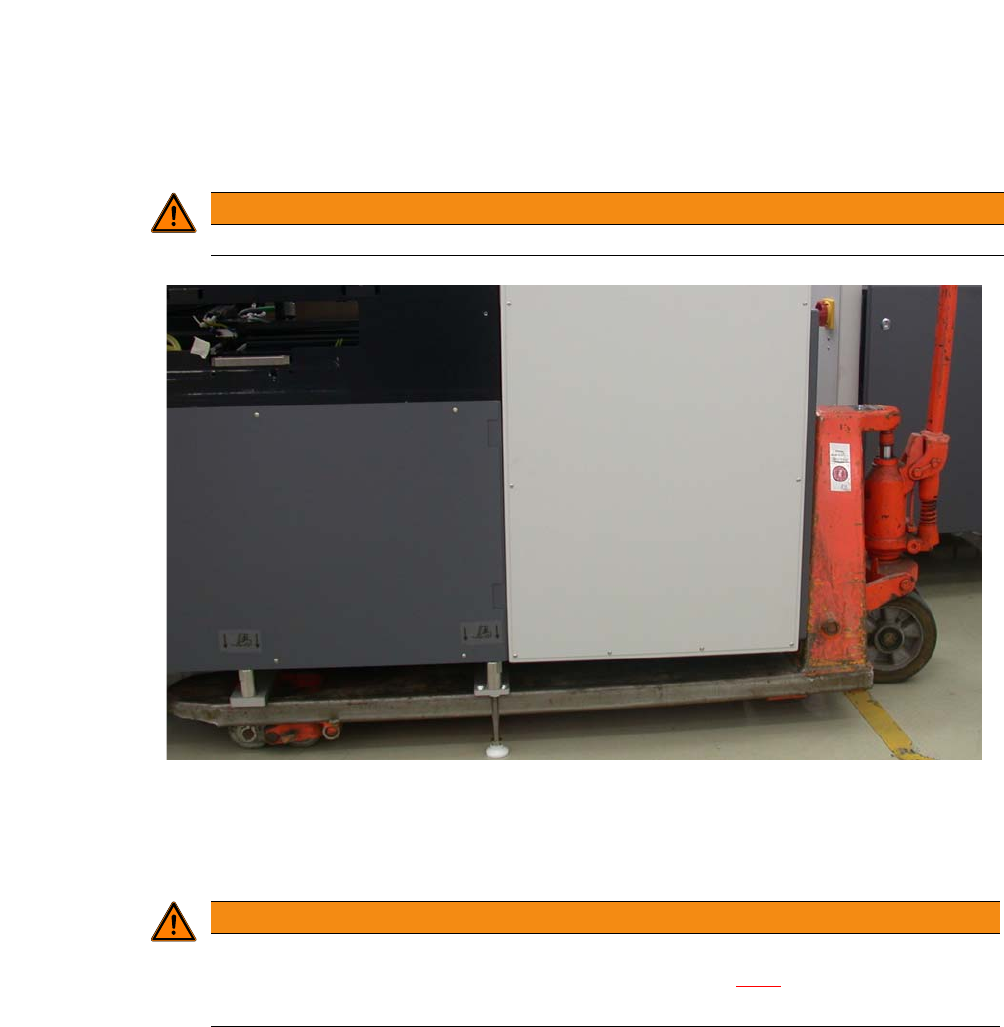
5.3.3.3 Fork Lift Attachment Points on the SWS
5
. 5
Fig. 5.3 - 2 Attachment points for fork-lift or hand lift on SWS
5.3.3.4 Points to be Observed While Transporting the SWS
5
WARNING
Only lift the SWS by its metal frame.
WARNING
Center of Gravity for SWS
Keep an eye on the SWS center of gravity (see section 3.4.8), particularly when mov-
ing it sideways.

5 Setting up and Commissioning User Manual SIPLACE CA-Series
5.4 Infrastructure at the Installation Location From software version SC.708.0 Edition 12/2014 EN -DRAFT
270
5.4 Infrastructure at the Installation Location
5.4.1 Recommendations for Foundation Quality
The foundation on which the placement machine or SWS is installed should be firm and level, as
dynamic forces can cause vibrations when the placement machine is operated. The degree of vi-
bration depends on the construction of the foundation. The following are suitable provided that the
floor loading parameters, etc., are not exceeded:
– Reinforced concrete ceiling constructions, e.g. ceilings in production halls
– Reinforced concrete floor slabs, e.g. concrete floors in production halls without a basement
– Rooms with double floors, provided that a stable foundation is included in the space between
them. The same setup conditions apply to this intermediate foundation, which can be made
from steel girders or concrete.
5.4.1.1 Machine Weight and Floor Loading
The machine weight and floor loading values can be found in section 3.4.4, page 135.
5
5.4.1.2 Vibration Limits
The placement machine is not susceptible to floor vibrations but the following vibration limits
should still be observed.
5
5
Parameters Values
Third-octave spectral value of the vibration speed 5 - 100 Hz
v < 250 µm/s
v
max
value on the time curve v
max
< 1.5 mm/s

User Manual SIPLACE CA-Series 5 Setting up and Commissioning
From software version SC.708.0 Edition 12/2014 EN -DRAFT 5.4 Infrastructure at the Installation Location
271
5.4.2 Compressed Air Supply
5.4.2.1 Checking the Compressed Air Supply
Check whether the compressed air supply complies with the prescribed machine specifications
(see table in section 3.3
, page 126).
5
Record the compressed air characteristics at the installation location.
PLEASE NOTE
Required specifications
To fulfill the required specifications, certain measures are described in the "Network Con-
figuration (Electrics and Compressed Air) for SMD Systems at Customer Site" documen-
tation [00191409-xx].