00197498-03_UM_SiplaceCA-Serie_EN.pdf - 第281页
User Manual SIPLACE CA-Series 5 Setting up and Commissioning From software version SC.708.0 Edition 12/20 14 EN -DRAFT 5.5 Setting Up the Placement Machine 281 5.5.4 Presetting Board Conveyor Height Insert the f orks o…
5 Setting up and Commissioning User Manual SIPLACE CA-Series
5.5 Setting Up the Placement Machine From software version SC.708.0 Edition 12/2014 EN -DRAFT
280
5
5
5.5.3 Tools and Equipment
You will need the following tools and equipment to adjust the height of the placement machine:
– Fork wrench SW 36 [00096286-01]
Wrench of width 36 for the setting screw M24x2x120 used to adjust the height of the ma-
chine feet. 5
– Hook wrench 135 - 145 for adjusting the middle machine feet [00376519-xx]
– Single head wrench SW 65 [00353827-01]
Size 65 for the hexagon lock nut M24 on the middle machine foot 5
– Allen keys, size 10 [00373926-01]
for hexagon socket head screws M12x80 for fixing the spacers for the middle machine feet5
– Allen keys, size 19 [00373928-01]
for hexagon socket head screw M24x90 for temporarily clamping the four outer machine
feet clamps 5
– Torque wrench with hexagonal pin, size 19, tightening torque 130 Nm
for final fastening of four outer machine feet
– Fork lift truck
Fork length: Min. 1,800 mm 5
Lifting power: Min. 6,000 kg 5
Width between forks: See fig. 5.5 - 1
5
– Machine spirit level: accuracy 0.02 mm/m
– Air cushion transport system: SIPLACE HSxx [00119002-xx]
WARNING
Height adjustment of machine!
Two people will be needed to adjust the height of the machine:
– One person completes the required assembly work
– The other person watches the stability of the raised placement machine during
assembly.
WARNING
DANGER OF CRUSHING!
One machine foot weighs 6.75 kg. There is a risk of crushing your feet when transporting
the machine.
Wear specially reinforced shoes.
User Manual SIPLACE CA-Series 5 Setting up and Commissioning
From software version SC.708.0 Edition 12/2014 EN -DRAFT 5.5 Setting Up the Placement Machine
281
5.5.4 Presetting Board Conveyor Height
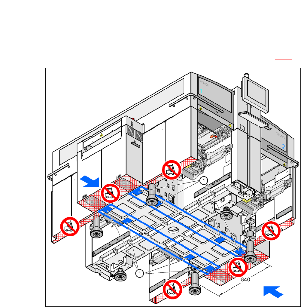
Insert the forks of the fork-lift truck under the placement machine, as shown in fig. 5.5 - 1.
5
Fig. 5.5 - 1 Contact surfaces - forks parallel to the direction of PCB transport
(1) Contact surfaces for fork lift truck forks
5 Setting up and Commissioning User Manual SIPLACE CA-Series
5.5 Setting Up the Placement Machine From software version SC.708.0 Edition 12/2014 EN -DRAFT
282
5
5
5
5
Lift the placement machine about 35 cm with the fork-lift truck. This prevents the risk of any
injuries to your feet if the machine feet are unintentionally lowered.
The placement machine stands on 6 feet.
– 4 outer machine feet (item 1 in fig. 5.5 - 3
, page 284)
The outer machine feet are available in two versions: 5
– Outer machine foot for PCB conveyor heights 900, 930 and 950 mm, Length 439 mm
[03000890-02] (item 2 in fig. 5.5 - 2
).
– 2 middle machine feet (item 2 in fig. 5.5 - 3
, page 284) with 2 spacers (item 3 and 4 in fig. 5.5
- 3, page 284) for height adjustment, where necessary.
WARNING
Please note the following points before you raise the machine, in order to avoid irre-
versible damage to the machine.
WARNING
Risk of damage due to excessive fork spacing!
The distance between the machine feet is 776 mm. Increased fork spacing, which means
that the machine is raised at points outside its contact surface, could lead to deformation
of the machine frame and cause damage to cables and lines.
The forks may only be opened to a degree which ensures that they are still within the
contact area of the machine underside (for contact surfaces see fig. 5.5 - 1
, page
281
).
WARNING
Risk of damage due to one-sided loading!
One-sided loading of the machine feet e.g. from tilting the machine, could lead to defor-
mation of the machine feet.
Make sure that the forks are evenly loaded when you lift the machine.
Use a firm support layer between the forks and the machine.
Enlist the help of a second person to watch while you lift the machine and make sure
that the machine does not tip over to one side.