00197498-03_UM_SiplaceCA-Serie_EN.pdf - 第286页
5 Setting up and Commissioning User Manual SIPLACE CA-Series 5.5 Setting Up the Placement Machine From software version SC.708.0 Edition 12/2014 EN -DR AFT 286 Setting a Board Conveyor Height of 930 and 950 mm 5 Y ou als…
User Manual SIPLACE CA-Series 5 Setting up and Commissioning
From software version SC.708.0 Edition 12/2014 EN -DRAFT 5.5 Setting Up the Placement Machine
285
5.5.4.1 Presetting the Height of the Middle Machine Feet
The middle machine feet are initially preset. Depending on the placement machine height, you
may need to screw the spacer to the underside of the machine.
Setting a Board conveyor Height of 900 mm 5
You need a spacer for a board conveyor height of 900 mm.
Make sure that the 90 mm side of the spacer is vertically aligned and the hole for the middle
machine foot indicates downwards.
5
5
5
5
5
5
5
5
5
5
5
5
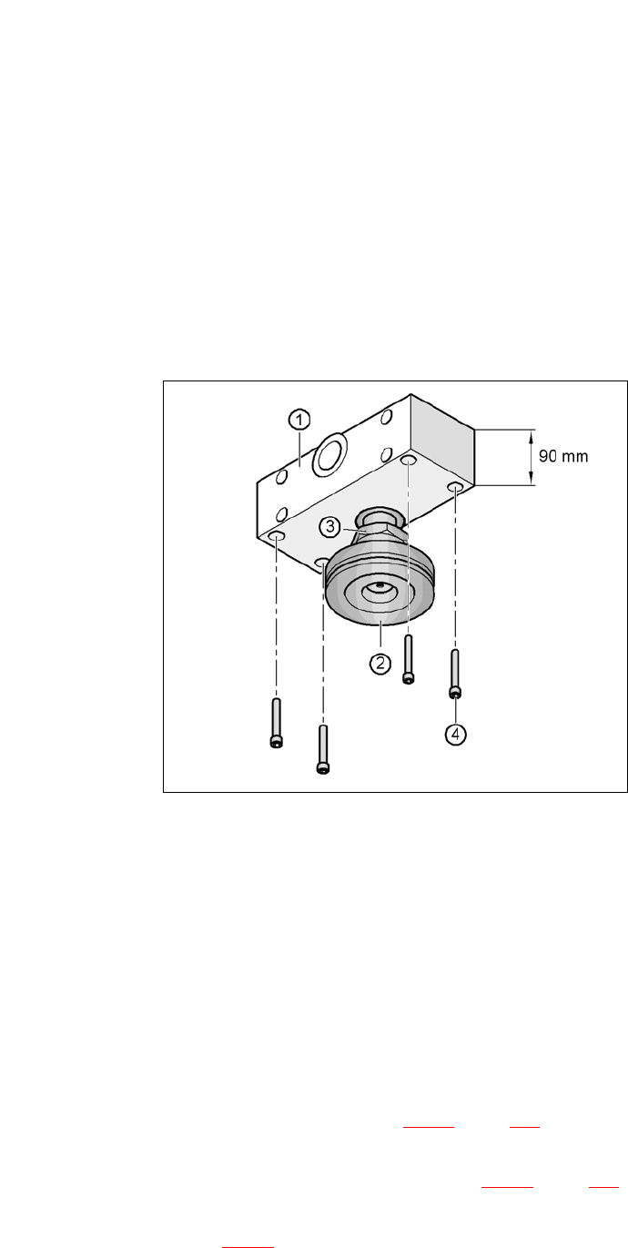
Fig. 5.5 - 4 Aligning the spacer for a conveyor height of 900 mm
5
(1) Spacer height of 90 mm
(2) Middle machine foot
(3) Lock nut M24
(4) Hexagon socket head screw M12x80, 4
Screw the thread of the middle machine foot into the hole provided on the underside of the
spacer.
Align the two spacers on the machine underside as follows:
– The spacer opening on the pneumatic unit side points in the direction of board conveyor
travel (see item 4 in fig. 5.5 - 3
, page 284).
– The spacer opening on the power supply side points in the opposite direction to that of
conveyor travel (see item 3 in fig. 5.5 - 3
, page 284).
Fasten each of the two spacers with four hexagon socket-head screws M12x80 (see item 4
in fig. 5.5 - 4
). Use the screwdriver bit of size 10 mm.
5 Setting up and Commissioning User Manual SIPLACE CA-Series
5.5 Setting Up the Placement Machine From software version SC.708.0 Edition 12/2014 EN -DRAFT
286
Setting a Board Conveyor Height of 930 and 950 mm 5
You also need the spacer for the board conveyor heights 930 mm and 950 mm.
Make sure that the 122.5 mm side of the spacer is vertically aligned and the hole for the mid-
dle machine foot indicates downwards.
5
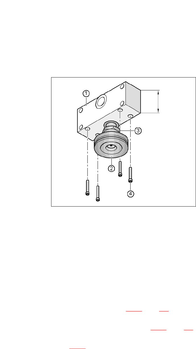
Fig. 5.5 - 5 Aligning the spacer for a conveyor heights of 930 and 950 mm
5
(1) Spacer height of 122.5 mm
(2) Machine foot
(3) Lock nut M24
(4) Hexagon socket head screw M12x80, 4
Screw the thread of the middle machine foot into the hole provided on the underside of the
spacer.
Align both spacers as follows:
– The spacer opening on the pneumatic unit side points in the direction of board conveyor
travel (see item 4 in fig. 5.5 - 3
, page 284).
– The spacer opening on the power supply side points in the opposite direction to that of
conveyor travel (see item 3 in fig. 5.5 - 3
, page 284).
Fasten each of the two spacers with four hexagon socket-head screws M12x80 (see item 4
in fig. 5.5 - 5
). Use the screwdriver bit of size 10 mm.
122.5 mm
User Manual SIPLACE CA-Series 5 Setting up and Commissioning
From software version SC.708.0 Edition 12/2014 EN -DRAFT 5.5 Setting Up the Placement Machine
287
5.5.4.2 Presetting the Height of the Outer Machine Feet
5
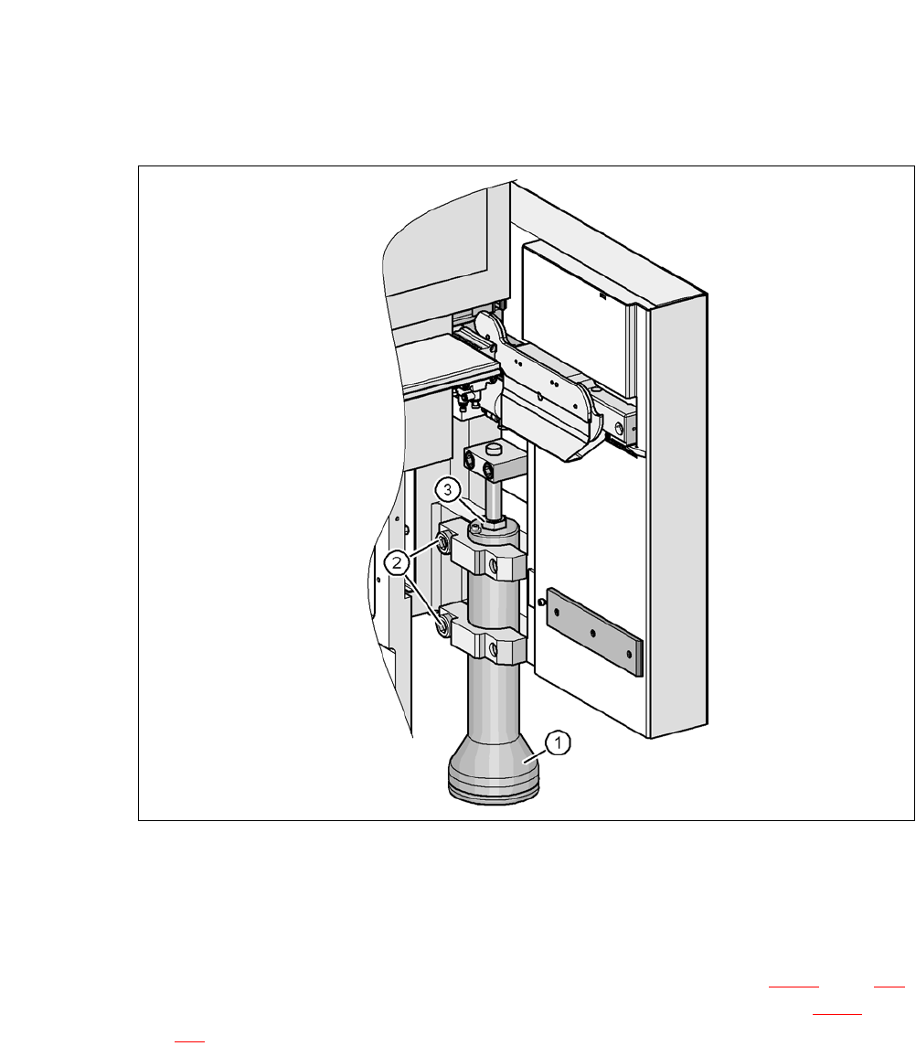
Fig. 5.5 - 6 Presetting the height of the outer machine feet
(1) Machine feet, - 2 versions
(2) Hexagon socket-head screw M24x90
(3) M24x2x120 adjusting screw
Carefully loosen both hexagon socket-head screws M24x90 (item 2 in fig. 5.5 - 6, page 287)
with the screwdriver bit (size 19 mm) and let the outer machine foot (item 1 in fig. 5.5 - 6
, page
287
) slowly slide down as far as the end stop.