00197498-03_UM_SiplaceCA-Serie_EN.pdf - 第297页
User Manual SIPLACE CA-Series 5 Setting up and Commissioning From software version SC.708.0 Edition 12/20 14 EN -DRAFT 5.5 Setting Up the Placement Machine 297 5.5.7.7 Inst alling the Bottom Hand Guard The placement mach…
5 Setting up and Commissioning User Manual SIPLACE CA-Series
5.5 Setting Up the Placement Machine From software version SC.708.0 Edition 12/2014 EN -DRAFT
296
5
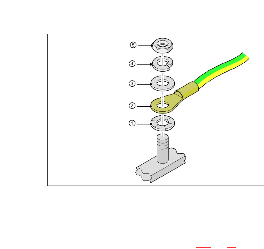
Fig. 5.5 - 10 Fitting the grounding cable
5
5
5
5
5
5.5.7.6 Checking and Setting the Protective Cover Switch
Check the function of the protective cover switch (item 7 in fig. 5.5 - 9, page 294).
Adjust the protective cover switch if necessary (see service manual).
Hex nut M
Spring washer M, DIN 7980
Washer M, DIN 125
Cable lug, annular
Contact washer
User Manual SIPLACE CA-Series 5 Setting up and Commissioning
From software version SC.708.0 Edition 12/2014 EN -DRAFT 5.5 Setting Up the Placement Machine
297
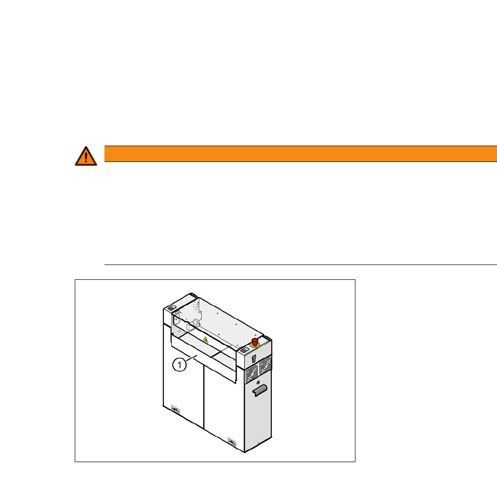
5.5.7.7 Installing the Bottom Hand Guard
The placement machines are only supplied with one bottom hand guard. However, if the place-
ment machines are installed in a line, there will be no hand guard between neighboring output and
input conveyors.
5
5
Fig. 5.5 - 11 Fitting the "bottom" hand guard to the PCB output side
(1) "Bottom" hand guard [03003432-01]
WARNING
Unauthorized Access!
A missing hand guard between the input and output sides of the placement machine in a
production line could lead to unauthorized access if staff reach into the inside of the place-
ment machine.
Always fit the bottom hand guard at the input side of the first placement machine and
on the output side of the last placement machine in a line [03003432-01] with 4 hexa-
gon socket-head screws M4x12.
5 Setting up and Commissioning User Manual SIPLACE CA-Series
5.5 Setting Up the Placement Machine From software version SC.708.0 Edition 12/2014 EN -DRAFT
298
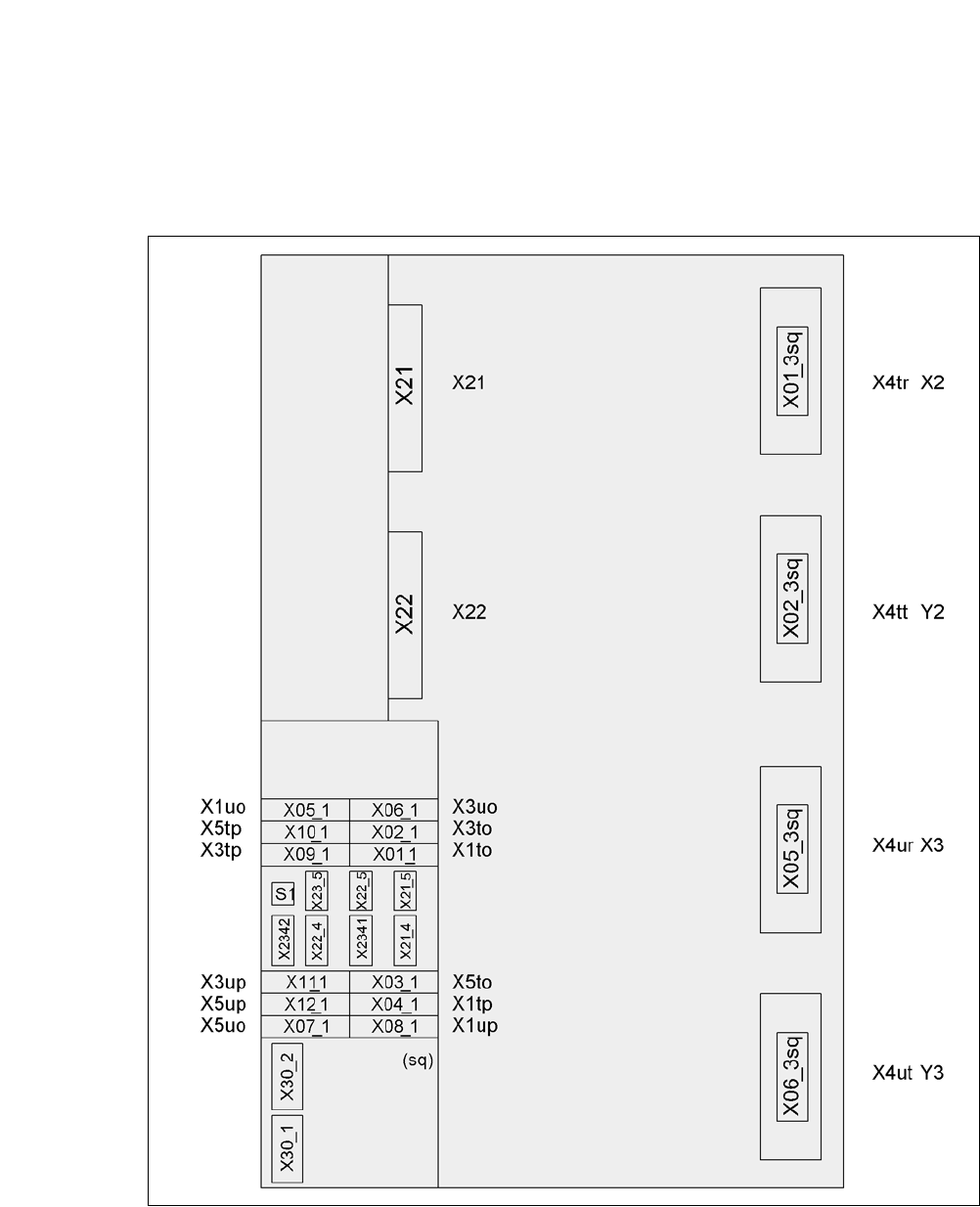
5.5.8 Installing the Axis Unit in the CA4
5.5.8.1 Axis Unit CA4 (Gantries 2 and 3) - Electrical Connection Points
5
Fig. 5.5 - 12 Axis unit CA4 (gantries 2 and 3), rear side - electrical connection points
Plug Plug
Plug