00197498-03_UM_SiplaceCA-Serie_EN.pdf - 第301页
User Manual SIPLACE CA-Series 5 Setting up and Commissioning From software version SC.708.0 Edition 12/20 14 EN -DRAFT 5.5 Setting Up the Placement Machine 301 5.5.9 Fitting the Input Conveyor 5.5.9.1 T ools – Allen keys…

5 Setting up and Commissioning User Manual SIPLACE CA-Series
5.5 Setting Up the Placement Machine From software version SC.708.0 Edition 12/2014 EN -DRAFT
300
5.5.8.3 Fitting the Axis Unit
Carefully lift the axis unit onto the rail in the extension kit.
Make sure that you do not squash any cables.
Push the axis unit into the extension kit as far as the stop.
Secure the axis unit with the fillister head screw.
Insert the cover.
Fasten the ground cable to the door (item 2 in fig. 5.5 - 8, page 292), as shown in fig. 5.5 - 10
on page 296
.
Lock the doors.
5.5.8.4 Fitting the Side Plates
Fasten the ground cable to each side plate (item 6 in fig. 5.5 - 8, page 292), as shown in fig.
5.5 - 10
page 296.
Fix the side plate to the machine frame with 6 fillister head screws.
5
5
PLEASE NOTE
Input conveyor dismantled
Continue with section 5.5.9 " Fitting the Input Conveyor" on page 301.
PLEASE NOTE
Input conveyor fitted
Continue with assembly work, as described in section 5.5.14 "Fitting the Main Fault
Indicators" on page 321.
User Manual SIPLACE CA-Series 5 Setting up and Commissioning
From software version SC.708.0 Edition 12/2014 EN -DRAFT 5.5 Setting Up the Placement Machine
301
5.5.9 Fitting the Input Conveyor
5.5.9.1 Tools
– Allen keys, DIN 911, set
– Phillips screwdriver, size 1
5.5.9.2 Assembly
5
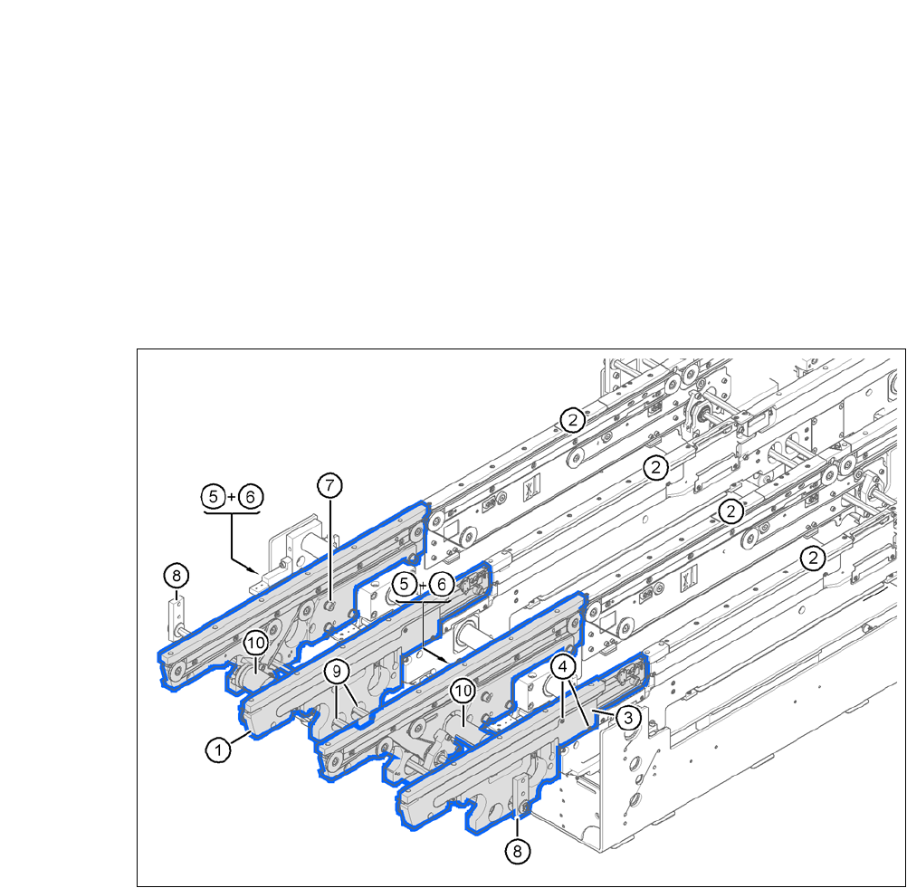
Fig. 5.5 - 13 Input conveyor - dual conveyor
(1) Side panel, input conveyor
(2) Side panel, processing conveyor 1
(3) Cable cover 20 x 200
(4) Countersunk screw, ISO 7046, M3x6, 2x per cable cover
(5) Cable cover 20 x 310
(6) Fillister head screw DIN 912, M3x5, 1x per cable cover
(7) Fillister head screw DIN 912, M6x16, and washer, 4 per panel
(8) Hexagonal shaft guidance
(9) Hexagonal shaft (single conveyor: one, dual conveyor: two)
(10) Drive unit
5 Setting up and Commissioning User Manual SIPLACE CA-Series
5.5 Setting Up the Placement Machine From software version SC.708.0 Edition 12/2014 EN -DRAFT
302
Dismantle the cable covers (item 3 and 5 in fig. 5.5 - 13) on the input conveyor (item 1 in fig.
5.5 - 13
).
Place the side (item 1 in fig. 5.5 - 13) carefully against the side of the processing conveyor
(item 2 in fig. 5.5 - 13
).
5
Fasten each side with 4 fillister head screws M6x16 and the corresponding discs (item 7 in
fig. 5.5 - 13
).
Connect the power cable to the light barriers and drive motors.
Fasten the cable covers (item 3 and 5 in fig. 5.5 - 13).
Insert the hexagonal shaft (item 9 in fig. 5.5 - 13) into the drive unit (item 10 in fig. 5.5 - 13).
Make sure that the hexagonal shaft guidance (item 8 in fig. 5.5 - 13) always points to the con-
veyor side to which the drive unit (item 10 in fig. 5.5 - 13
) is fixed.
CAUTION
Be careful not to cut through any of the light barrier or drive motor cables.