00197498-03_UM_SiplaceCA-Serie_EN.pdf - 第305页
User Manual SIPLACE CA-Series 5 Setting up and Commissioning From software version SC.708.0 Edition 12/20 14 EN -DRAFT 5.5 Setting Up the Placement Machine 305 5 Fig. 5.5 - 15 Fitting the conveyor cove r and the second h…
5 Setting up and Commissioning User Manual SIPLACE CA-Series
5.5 Setting Up the Placement Machine From software version SC.708.0 Edition 12/2014 EN -DRAFT
304
Remove both side plates (item 6 in fig. 5.5 - 14).
5
Detach the ground cable from the side plate.
Remove both doors (item 2 in fig. 5.5 - 14) from the extension kit (item 1).
5
Place the computer unit/box PC unit (item 8 in fig. 5.5 - 14) and the axis unit (item 9 in fig. 5.5
- 14) down to one side of the placement machine, leaving enough room to fit the extension kit
(item 1 in fig. 5.5 - 14
).
Make sure that the connection cable to the computer unit / Box PC unit and the axis unit is
not under tension.
Lift one half of the extension kit (item 1 in fig. 5.5 - 14) up to the machine frame and position
these so that the assembly bracket lies on the unit rail (item 7 in fig. 5.5 - 14
).
5
Fasten this half of the extension kit with 2 fillister head screws M6x16 and the corresponding
discs (item 3 in fig. 5.5 - 14
).
Before assembling the second half of the extension kit, fit the conveyor covers (item 5 in fig.
5.5 - 14
). The procedure is as follows:
CAUTION
Risk of injuries!
When you unscrew the three lower screws, the side panel could fall down and cause in-
juries.
Loosen the three lower screws but do not fully unscrew them for now.
PLEASE NOTE
Avoiding damage
To avoid damage, we recommend that a second person helps to assemble the extension
kit.
CAUTION
Risk of collisions!
Half of the extension kit could collide with the hexagonal shaft of the PCB conveyor. The
hexagonal shaft could be bent.
Make sure that this half of the extension kit does not collide with the hexagonal shaft
of the PCB conveyor and thus bend the shaft.
User Manual SIPLACE CA-Series 5 Setting up and Commissioning
From software version SC.708.0 Edition 12/2014 EN -DRAFT 5.5 Setting Up the Placement Machine
305
5
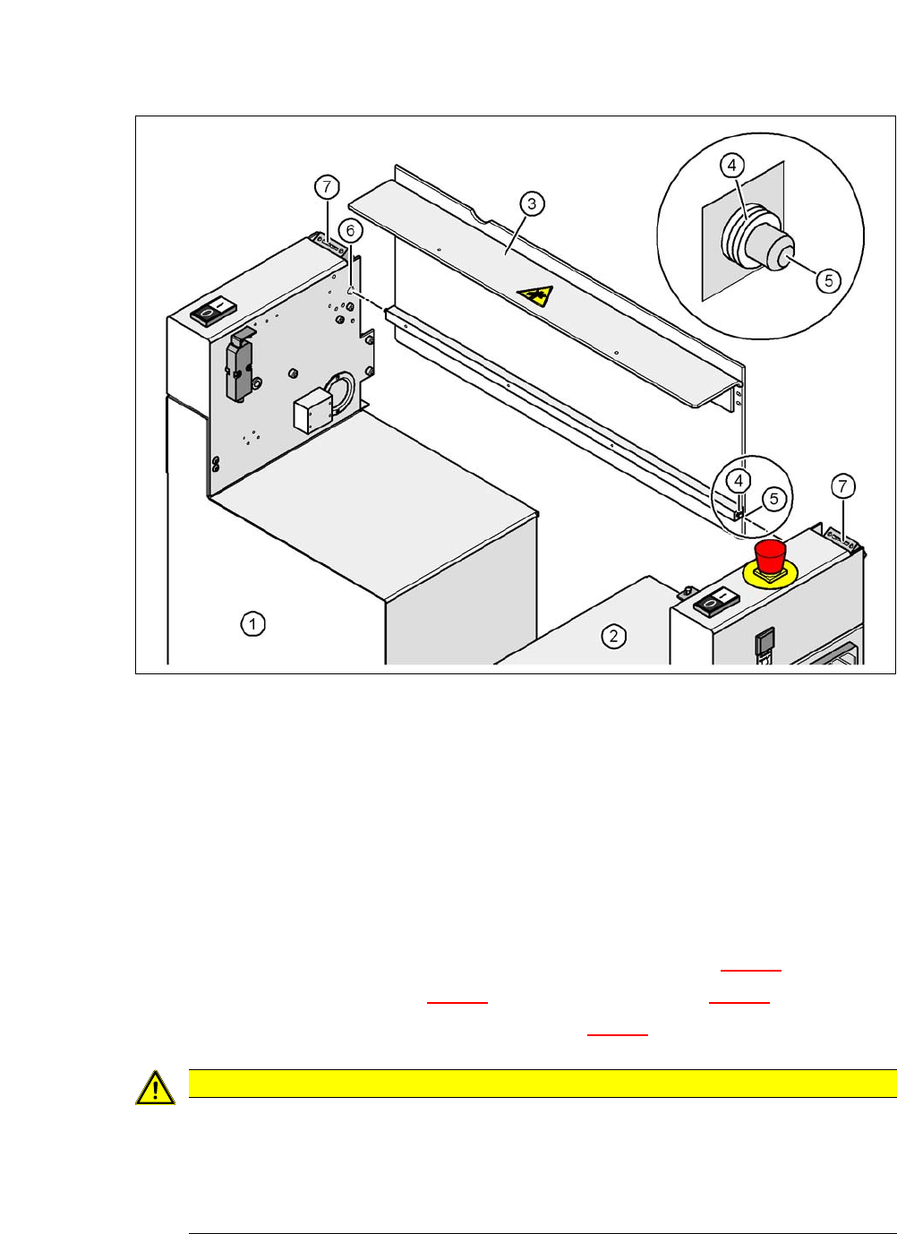
Fig. 5.5 - 15 Fitting the conveyor cover and the second half of the extension kit
(1) Half of the extension kit already fitted
(2) Second half of the extension kit to be fitted
(3) Transport cover
(4) Insert 3 white plastic washers on both sides
(5) Mandrel of the conveyor cover
(6) Hole
(7) Protective cover switch
Insert 3 white plastic discs on each of the two mandrels (item 5 in fig. 5.5 - 15).
Insert the mandrel (item 5 in fig. 5.5 - 15) into the hole (item 6 in fig. 5.5 - 15).
Lift the second half of the extension kit (item 2 in fig. 5.5 - 15) up to the machine frame.
5
CAUTION
Risk of collisions!
Half of the extension kit could collide with the hexagonal shaft of the PCB conveyor. The
hexagonal shaft could be bent.
Make sure that this half of the extension kit does not collide with the hexagonal shaft
of the PCB conveyor and thus bend the shaft.

5 Setting up and Commissioning User Manual SIPLACE CA-Series
5.5 Setting Up the Placement Machine From software version SC.708.0 Edition 12/2014 EN -DRAFT
306
Insert the mandrel (item 5 in fig. 5.5 - 15) for the transportation cover into the hole (item 6 in
fig. 5.5 - 15
) for the second half of the extension kit.
Position the second half of the extension kit so that the assembly bracket lies on the assembly
bar (item 7 in fig. 5.5 - 14
).
Fasten this second half of the placement machine with 2 fillister head screws M6x16 and the
corresponding washer (item 3 in fig. 5.5 - 14
).
5.5.10.3 Fastening the Hexagonal Shaft Guidance
When using a single conveyor, fasten one guidance for the hexagonal shaft (item 8 in fig. 5.5
- 13) to the extension kit with two fillister head screws M6x16 and washers
When using a dual conveyor, fasten two guidances for the hexagonal shaft (item 8 in fig. 5.5
- 13) to the extension kit with two fillister head screws M6x16 and washers.
5.5.10.4 Establishing Cable Connections - Extension Kit on the PCB Input Side
5
Left side of extension kit
(viewed in direction of transport)
Connector/cable To connector/
cable
Start/Stop button
Switch, PCB conveyor cover
X61/03020410 X61/03002537
Protective cover switch, location 4 X54/03020409 X54/03002540
Button for the COT insert, location 4 X242/03021056 X242/03021054
Right side of extension kit
(viewed in direction of transport)
Connector/cable To connector/
cable
EMERGENCY STOP button
Start/Stop button
X64/03020687 X64/03002538
Protective cover switch, location 1 X51/03020409 X51/03002539
Button for the COT insert, location 1 X212/03021056 X212/03021051