00197498-03_UM_SiplaceCA-Serie_EN.pdf - 第314页
5 Setting up and Commissioning User Manual SIPLACE CA-Series 5.5 Setting Up the Placement Machine From software version SC.708.0 Edition 12/2014 EN -DR AFT 314 5.5.12 Inst alling th e Computer Unit for the CA4 5.5.12.1 C…

User Manual SIPLACE CA-Series 5 Setting up and Commissioning
From software version SC.708.0 Edition 12/2014 EN -DRAFT 5.5 Setting Up the Placement Machine
313
5.5.11.5 Fitting the Side Plates
Fasten the ground cable to each side plate (item 6 in fig. 5.5 - 14, page 303), as shown in fig.
5.5 - 16
page 307.
Fix the side plate to the machine frame with 6 fillister head screws.
Continue with section 5.5.14 " Fitting the Main Fault Indicators", page 321.
5 Setting up and Commissioning User Manual SIPLACE CA-Series
5.5 Setting Up the Placement Machine From software version SC.708.0 Edition 12/2014 EN -DRAFT
314
5.5.12 Installing the Computer Unit for the CA4
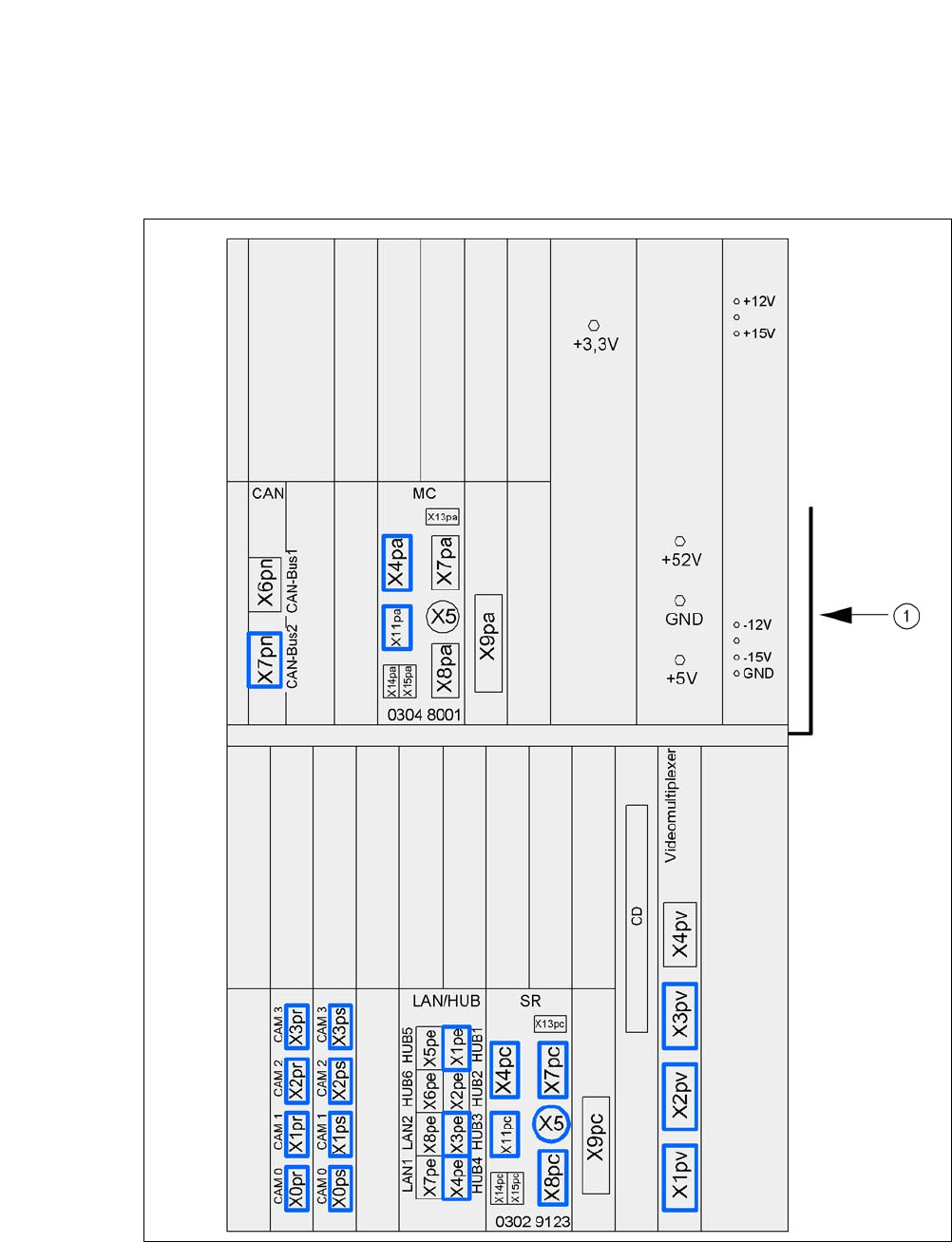
5.5.12.1 Computer Unit - Electrical Connection Points
5
Fig. 5.5 - 20 Computer unit, front - connecting plugs
(1) Cable guide plate
User Manual SIPLACE CA-Series 5 Setting up and Commissioning
From software version SC.708.0 Edition 12/2014 EN -DRAFT 5.5 Setting Up the Placement Machine
315
5
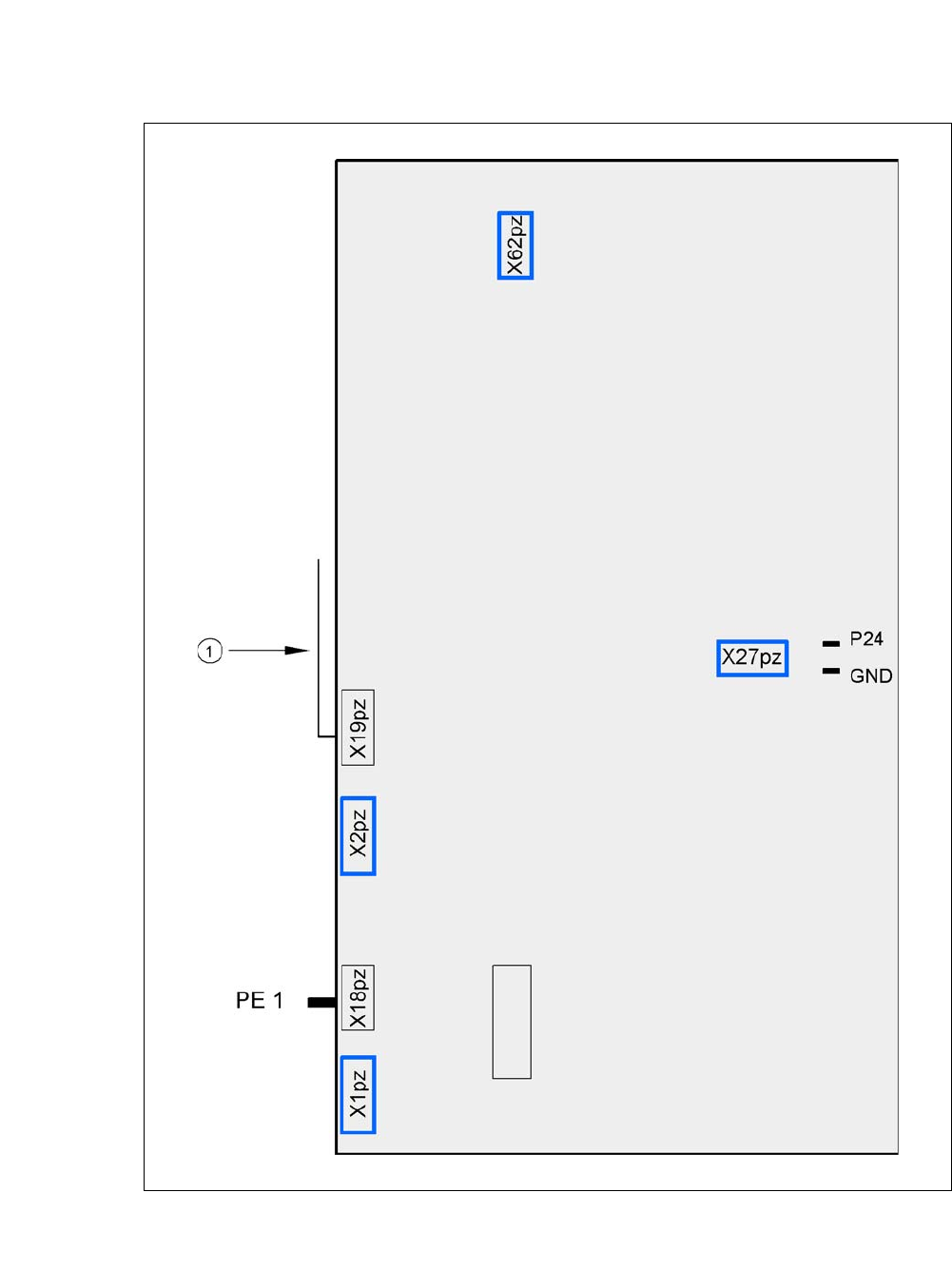
Fig. 5.5 - 21 Computer unit, back - connecting plugs
(1) Cable guide plate
Fan
Battery
+3.6V