00197498-03_UM_SiplaceCA-Serie_EN.pdf - 第322页
5 Setting up and Commissioning User Manual SIPLACE CA-Series 5.5 Setting Up the Placement Machine From software version SC.708.0 Edition 12/2014 EN -DR AFT 322 5 Fig. 5.5 - 23 Fitting the main indicator lamp (1) Main ind…

User Manual SIPLACE CA-Series 5 Setting up and Commissioning
From software version SC.708.0 Edition 12/2014 EN -DRAFT 5.5 Setting Up the Placement Machine
321
5.5.13.3 Fitting the Axis Unit for the CA4 (Gantry 1 and 4)
Carefully lift the axis unit onto the rail in the extension kit.
Make sure that you do not squash any cables.
Push the axis unit into the extension kit as far as the stop.
Secure the axis unit with the fillister head screw.
Insert the cover.
Fasten the ground cable to the door (item 2 in fig. 5.5 - 14, page 303), as shown in fig. 5.5 -
16 on page 307.
Lock the doors.
5.5.13.4 Fitting the Side Plates
Fasten the ground cable to each side plate (item 6 in fig. 5.5 - 14, page 303), as shown in fig.
5.5 - 16
page 307.
Fix the side plate to the machine frame with 6 fillister head screws.
5.5.14 Fitting the Main Fault Indicators
Connect the main fault indicator cables to the cables on the basic machine.
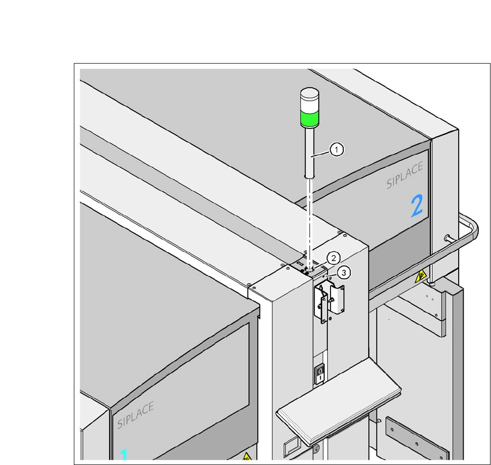
Insert the main fault indicator into the hole (item 2 in fig. 5.5 - 23, page 322) until the tube of
the main fault indicator lamp is pushed far enough into the terminal below.
Tighten the hexagon socket-head screw under the hole (item 3 in fig. 5.5 - 23, page 322).
5 Setting up and Commissioning User Manual SIPLACE CA-Series
5.5 Setting Up the Placement Machine From software version SC.708.0 Edition 12/2014 EN -DRAFT
322
5
Fig. 5.5 - 23 Fitting the main indicator lamp
(1) Main indicator lamp
(2) Hole for the main indicator lamp
(3) Hole for the locking screw
5.5.15 Fastening the Monitor
Fix the monitor into place and connect the cables.
Check the cable connections
User Manual SIPLACE CA-Series 5 Setting up and Commissioning
From software version SC.708.0 Edition 12/2014 EN -DRAFT 5.5 Setting Up the Placement Machine
323
5.5.16 Integrating the Placement Machine into the Line
Observe the general warnings in section 5.5.2, page 279.
For details of tools and equipment, refer to section 5.5.3, page 280.
5.5.16.1 Positioning the Fork Lift
5
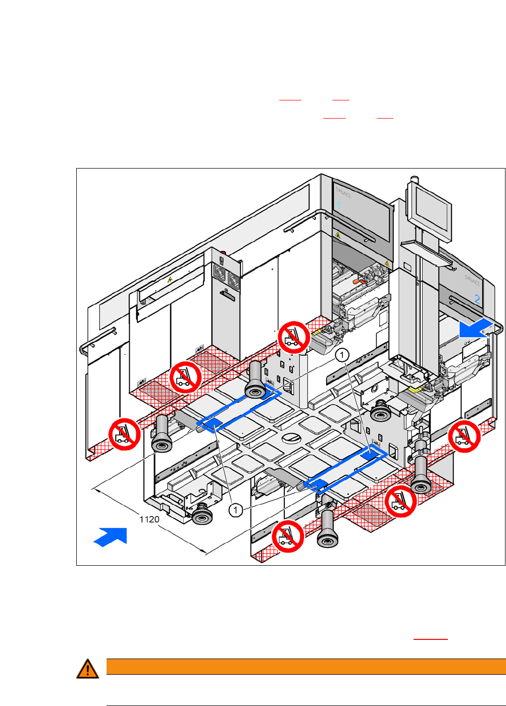
Fig. 5.5 - 24 Contact surfaces - Forks across the direction of PCB transport
(1) Contact surfaces for fork lift truck forks
Position the fork-lift truck at right angles to the PCB conveyor and open the forks until the con-
tact surfaces of the placement machine lie evenly on the forks (see fig. 5.5 - 24
).
5
WARNING
Please note the following points before you raise the machine, in order to avoid irre-
versible damage to the machine.