00197498-03_UM_SiplaceCA-Serie_EN.pdf - 第325页
User Manual SIPLACE CA-Series 5 Setting up and Commissioning From software version SC.708.0 Edition 12/20 14 EN -DRAFT 5.5 Setting Up the Placement Machine 325 5.5.16.3 Aligning the Placement Machine to the Line Positi…
5 Setting up and Commissioning User Manual SIPLACE CA-Series
5.5 Setting Up the Placement Machine From software version SC.708.0 Edition 12/2014 EN -DRAFT
324
5
5
5.5.16.2 Points To Be Observed When Transporting the Placement Machine
5
WARNING
Risk of damage due to excessive fork spacing!
The distance between the forks must be between 800 and 900 mm. The attachment points
for the fork-lift truck can be seen in fig. 5.2 - 4
. The outer distance between the contact
surfaces is 1,120 mm.
Increased fork spacing, which means that the machine is raised at points outside its con-
tact surface, could lead to deformation of the machine frame and cause damage to cables
and lines.
The forks may only be opened to a degree which ensures that they are still within the
contact area of the machine underside (for contact surfaces see fig. 5.2 - 3
).
WARNING
Risk of damage due to one-sided loading!
One-sided loading of the machine feet e.g. from tilting the machine, could lead to defor-
mation of the machine feet.
Make sure that the forks are evenly loaded when you lift the machine.
Use a firm support layer between the forks and the machine.
Enlist the help of a second person to watch while you lift the machine and make sure
that the machine does not tip over to one side.
WARNING
Risk of damage!
The thread for the machine feet in the machine frame could be damaged by being
dragged along the floor or from impact.
When you are transporting the machine, make sure that all the feet are clear of the
floor.
User Manual SIPLACE CA-Series 5 Setting up and Commissioning
From software version SC.708.0 Edition 12/2014 EN -DRAFT 5.5 Setting Up the Placement Machine
325
5.5.16.3 Aligning the Placement Machine to the Line
Position the placement machine with the fork-lift truck , so that it is in a free location in the line.
5
5
5.5.16.4 Aligning the Machine with the Air Cushion Transport System
Place the four air cushions of the air cushion transport system beneath the machine frame.
Lift the placement machine and align it to the line.
Check the distance to the PCB conveyor system of the neighboring placement machine. It
should be between 1 mm and 3 mm.
Lower the placement machine.
5
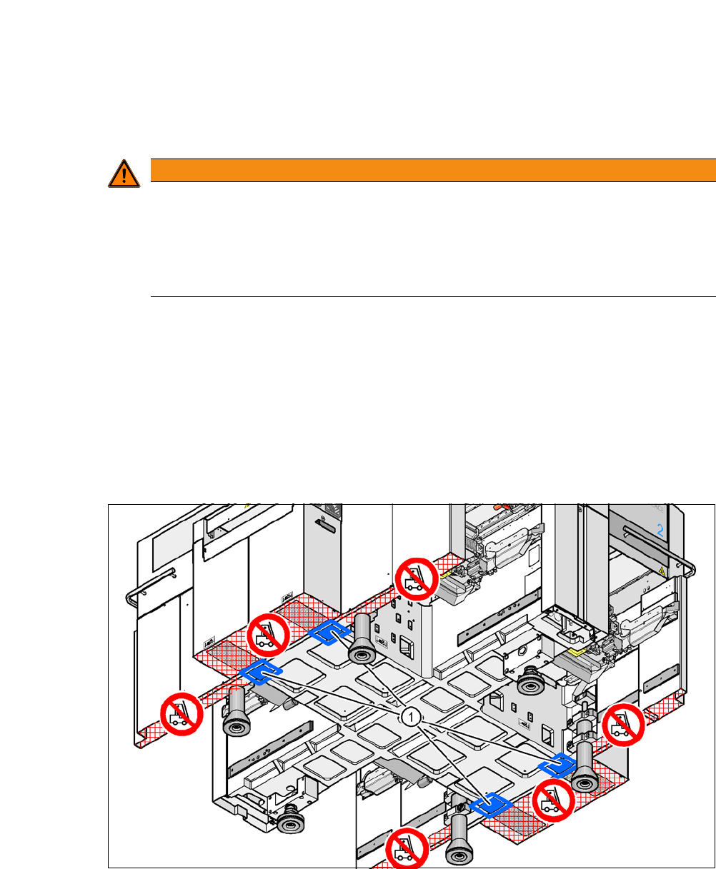
Fig. 5.5 - 25 Contact surfaces for the air cushion transport system
(1) Contact surfaces for the air cushion transport system
WARNING
Risk of damage!
If the machine feet on one side hit the ground hard, the fixings may be damaged.
Lower the machine slowly.
A second person should look underneath to ensure that all the machine foot touch
the floor at the same time.
5 Setting up and Commissioning User Manual SIPLACE CA-Series
5.5 Setting Up the Placement Machine From software version SC.708.0 Edition 12/2014 EN -DRAFT
326
5.5.17 Final Adjustment of Placement Machine
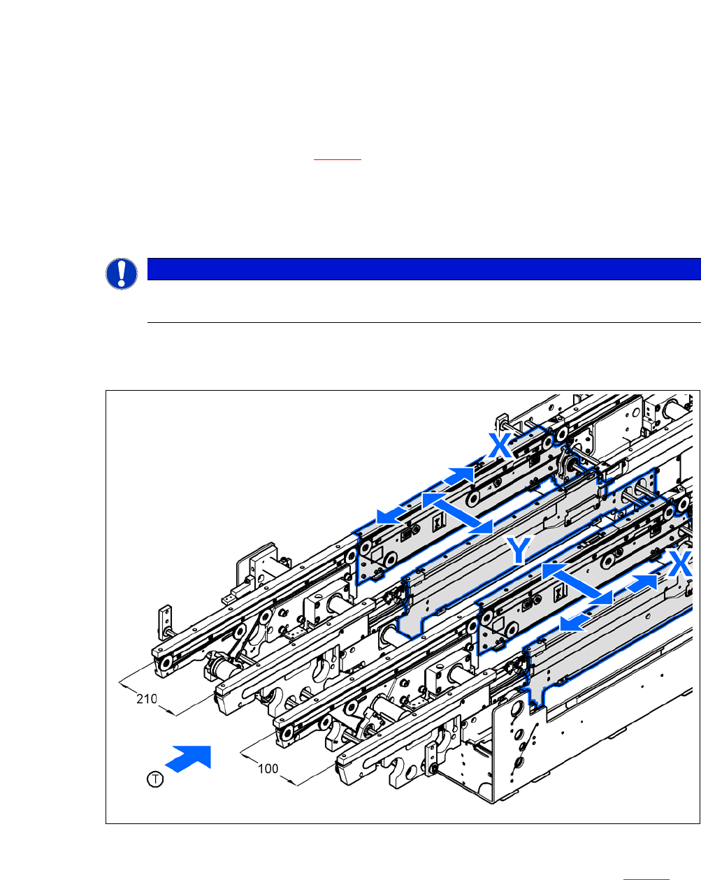
Place the machine spirit level in the X and then the Y direction on the sides of the conveyor
in placement area 1 (see fig. 5.5 - 26
). The board conveyor width has been preset:
Single conveyor 210 mm
Dual conveyor, lane 1 100 mm
Dual conveyor, lane 2 210 mm 5
5
Measure the distance between the upper edge of the PCB conveyor belt and the underside.
This distance should be 800 mm, 900 mm, 930 mm or 950 mm.
5
Fig. 5.5 - 26 Adjusting the placement machine in the X and Y directions
Use the fork wrench SW36 to adjust the setting screw M24x2x120 (item 1 in fig. 5.5 - 27), so
that the fluid in the machine spirit level does not deviate from its zero point at the required
conveyor height.
PLEASE NOTE
When using a dual conveyor, the spirit level for adjustment needs to be always placed
on the outer sides of the placement machine, when measuring in the X direction.