00197498-03_UM_SiplaceCA-Serie_EN.pdf - 第332页
5 Setting up and Commissioning User Manual SIPLACE CA-Series 5.6 Fitting the SWS From software version SC.708.0 Edition 12/2014 EN -DRAFT 332 5.6.3.2 Moving the SWS into the Placement Machine 5 5 Fig. 5.6 - 1 Connections…
User Manual SIPLACE CA-Series 5 Setting up and Commissioning
From software version SC.708.0 Edition 12/2014 EN -DRAFT 5.6 Fitting the SWS
331
5
5
5.6.2 Tools and Equipment
You will need the following tools and equipment to install the SWS:
– Standard tool
– Torque wrench
– Fork lift/hand lift (see section 5.3
), blocks for underneath if required
– Screwed feet
5.6.3 Installing the SWS in the Placement Machine
5.6.3.1 Positioning the Fork Lift
Position the fork-lift truck lengthwise under the SWS and open the forks until the contact sur-
faces of the SWS lie evenly on the forks. The magazine lift unit must be facing the forklift.
5
5
WARNING
DANGER OF CRUSHING!
Risk of crushing feet when transporting the SWS.
Wear specially reinforced shoes.
PLEASE NOTE
Please note that the SWS can only be fitted as follows:
– CA4 placement machine all locations (on the left-hand side for 1 and 3, on the right-
hand side for 2 and 4)
WARNING
Please note the following points before you raise the SWS, in order to avoid irrevers-
ible damage to the machine.
WARNING
Risk of damage due to one-sided loading!
One/sided loading of the machine feet e.g. from tilting the SWS, could lead to deformation
of the machine feet.
Make sure that the forks are evenly loaded when you lift the machine.
Use a firm support layer between the forks and the machine.
Enlist the help of a second person to watch while you lift the SWS and make sure that
the SWS does not tip over to one side.
5 Setting up and Commissioning User Manual SIPLACE CA-Series
5.6 Fitting the SWS From software version SC.708.0 Edition 12/2014 EN -DRAFT
332
5.6.3.2 Moving the SWS into the Placement Machine
5
5
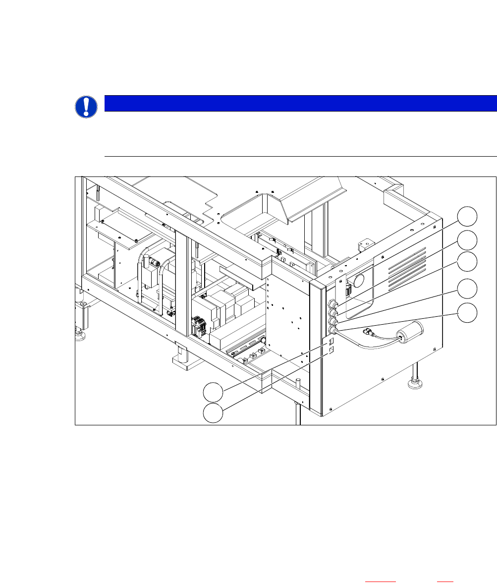
Fig. 5.6 - 1 Connections on the SWS
5
5
Push the fork of the fork lift truck under the SWS (see section 5.2.4.3 on page 262).
Lift the SWS and align it to the placement machine. If the lifting range of the hand lift is not
sufficient, use wooden blocks or a similar object.
PLEASE NOTE
Before inserting the SWS, make sure that the CAN Bus connection X1x5 and X1x6,
the compressed air connection and the FFI communication interface W11 on the
SWS are accessible.
(1) Manometer for compressed air supply (2) Voltage supply
(3) Communication with SIPLACE machine (4) CAN bus
(5) Compressed air connection (modified
adapter dummy connector [03011592-01])
(6) LAN1
(7) LAN2
2
1
3
4
5
6
7
User Manual SIPLACE CA-Series 5 Setting up and Commissioning
From software version SC.708.0 Edition 12/2014 EN -DRAFT 5.6 Fitting the SWS
333
5
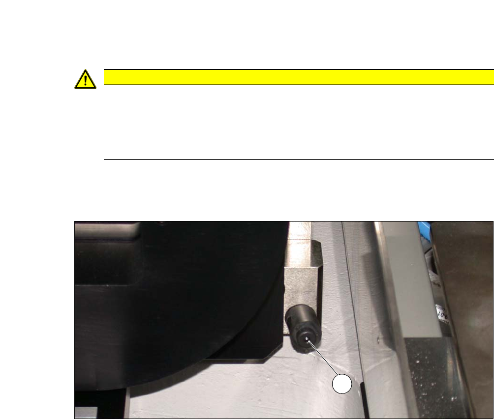
Carefully push the SWS into the placement machine, until it is approx. 30 cm before the
bumper (see following fig.), so that you still have enough room to connect the SWS and
placement machine connections.
5
Fig. 5.6 - 2 Bumper
(1) Bumper
CAUTION
Risk of collision!
The monitor of the SWS could hit the placement machine cover when moving into the ma-
chine.
Before inserting the SWS into the machine, open the SWS monitor, so that this can
not hit the cover of the placement machine.
1