00197498-03_UM_SiplaceCA-Serie_EN.pdf - 第341页
User Manual SIPLACE CA-Series 5 Setting up and Commissioning From so ftware ver sion SC.708.0 Edition 12/2014 EN -DRAFT 5.8 Adjusting the Length of the SIPLACE X Use d Tape Chute to the PCB Conveyor Height 341 5.8 Adjust…
5 Setting up and Commissioning User Manual SIPLACE CA-Series
5.7 Adapting the SIPLACE X-Series Component Trolley to the PCB Conveyor Height From software version SC.708.0 Edition 12/2014
EN -DRAFT
340
5
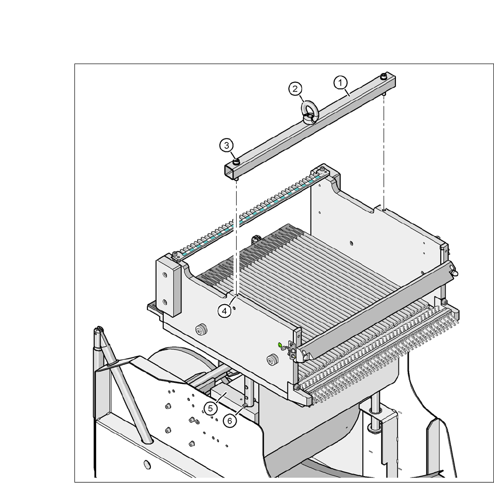
Fig. 5.7 - 2 Fastening the fit-up aid to the changeover table of the SIPLACE component trolley
(1) Fit-up aid
(2) Eyelet
(3) Hexagon socket-head screw DIN 912, M8 x 50, 2 x
(4) 2x M8 threaded hole in the component table
(5) Support block , 2x
(6) Split pin, DIN 7343, 8 x 40 - St, 2 x
User Manual SIPLACE CA-Series 5 Setting up and Commissioning
From software version SC.708.0 Edition 12/2014 EN -DRAFT 5.8 Adjusting the Length of the SIPLACE X Used Tape Chute to the PCB
Conveyor Height
341
5.8 Adjusting the Length of the SIPLACE X Used Tape
Chute to the PCB Conveyor Height
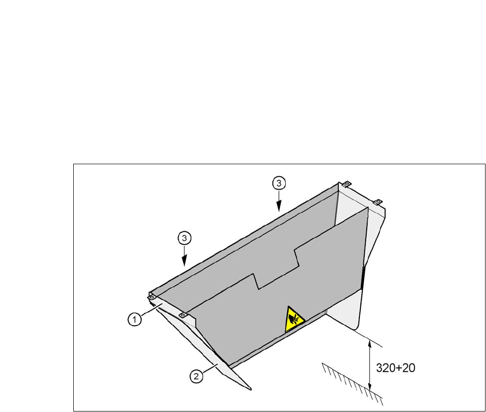
In accordance with the PCB conveyor height, the length of the used tape chute can be set so that
the tape cuttings are directly diverted into the waste tape container of the component trolley.
5
Fig. 5.8 - 1 Adapting the length of the used tape channel (X-Series) - Dimensions in millimeters
(1) Used tape chute
(2) Extension
(3) Hexagonal nut M4, DIN 985, 2 x
5.8.1 Tools
– Fork wrench, size 7

5 Setting up and Commissioning User Manual SIPLACE CA-Series
5.8 Adjusting the Length of the SIPLACE X Used Tape Chute to the PCB Conveyor Height From software version SC.708.0 Edition 12/
2014 EN -DRAFT
342
5.8.2 Setting the Length of the Used Tape Chute
5.8.2.1 PCB Conveyor Heights 900 mm - 950 mm
Loosen the two hexagonal nuts M4 (item 3 in fig. 5.8 - 1).
Adjust the extension (item 2 in fig. 5.8 - 1) so that the distance between the lower edge and
the ground are a maximum of 320 mm + 20 mm (see fig. 5.8 - 1
).