00197498-03_UM_SiplaceCA-Serie_EN.pdf - 第352页
6 Working with the Machine User Manual SIPLACE CA-Series 6.2 The User Interface From software version SC.708.0 Edition 12/2014 EN -DR AFT 352 The following view will open: 6 Fig. 6.2 - 3 User interface in the "Feede…
User Manual SIPLACE CA-Series 6 Working with the Machine
From software version SC.708.0 Edition 12/2014 EN -DRAFT 6.2 The User Interface
351
6.2.4 Operating the Station Software in the Views
Most views which can be accessed via the toolbar (see section 6.2.3, page 349) have an addi-
tional vertical toolbar with subviews and functions, on the right-hand side of the user interface.
6
Example: "Feeder modules, components and nozzles" view
Click on "Feeder modules, components and nozzles" in the toolbar .
PLEASE NOTE
For a detailed description of the individual functions refer to the Online Help.
6 Working with the Machine User Manual SIPLACE CA-Series
6.2 The User Interface From software version SC.708.0 Edition 12/2014 EN -DRAFT
352
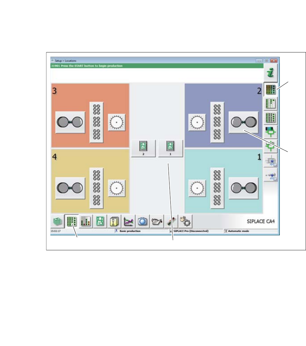
The following view will open:
6
Fig. 6.2 - 3 User interface in the "Feeder modules, components and nozzles" view (example of SIPLACE CA4
shown)
Legend
(1) Toolbar ("Feeder modules, components and nozzles" button)
(2) Vertical toolbar in "Feeder modules, component and nozzles" view
(3) Processing area with 4 gantries
(4) Button for SIPLACE Wafer System (SWS) at location 2
Click, for example, on the SIPLACE Wafer System (SWS) of gantry 1 (button 4), to open the
SWS functions.
(1)
(2)
(3)
(4)
User Manual SIPLACE CA-Series 6 Working with the Machine
From software version SC.708.0 Edition 12/2014 EN -DRAFT 6.2 The User Interface
353
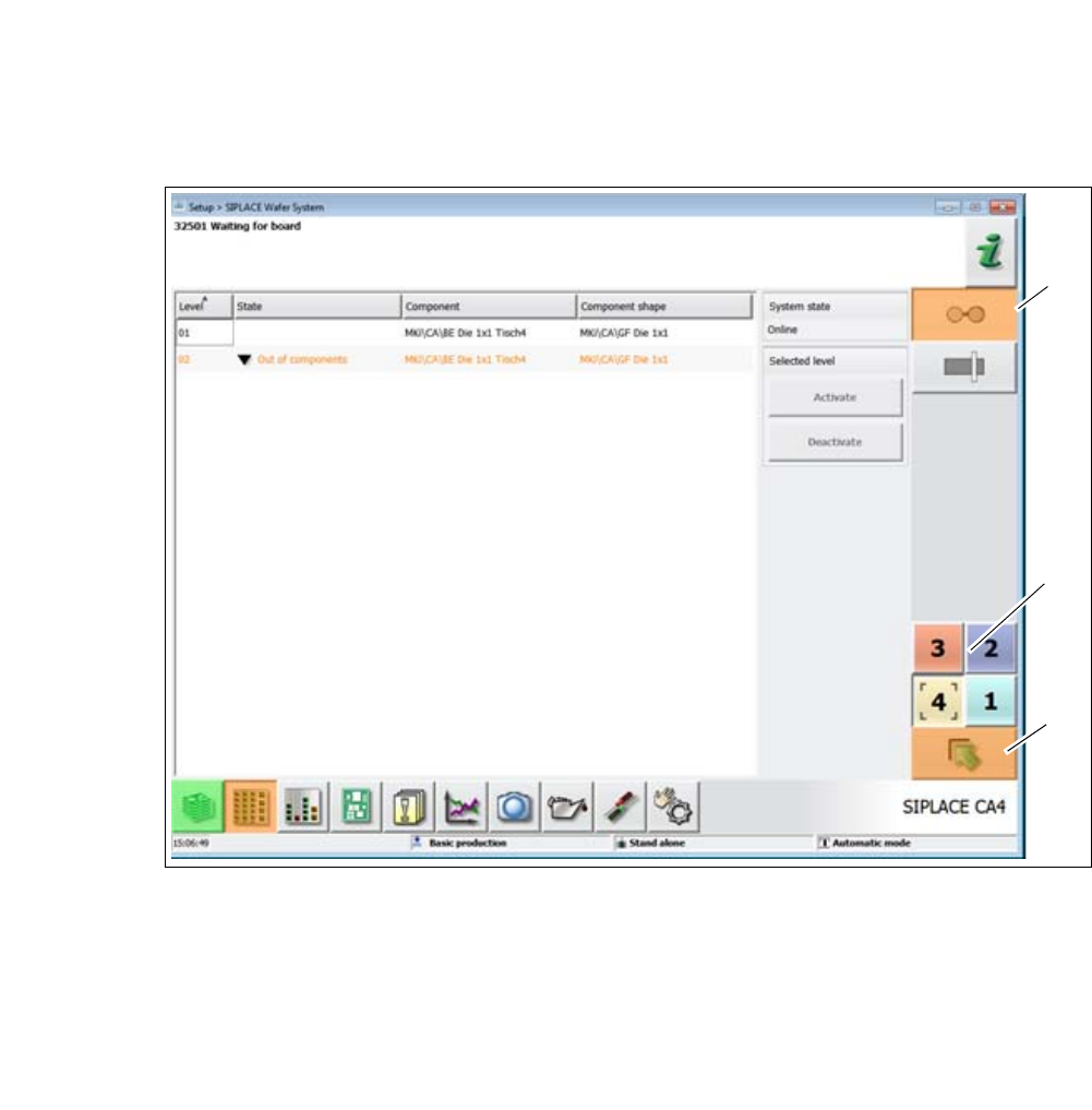
The following view will open:
6
Fig. 6.2 - 4 User interface in the "WPC" view (example of SIPLACE SX shown)
Legend
(1) Vertical toolbar for "SIPLACE Wafer System" functions
(2) Buttons for changing directly to a different gantry
(3) "Up one level" button, to return to previous view (here: "Feeder modules, component and
nozzles" view, see previous diagram)
(1)
(2)
(3)