00197498-03_UM_SiplaceCA-Serie_EN.pdf - 第358页
6 Working with the Machine User Manual SIPLACE CA-Series 6.4 SWS Tasks From software version SC.708.0 Edition 12/2014 EN -DRAFT 358 6.4.5 Setting up the Needle Conf iguration for the Ejection System In the SWS GUI, swi…
User Manual SIPLACE CA-Series 6 Working with the Machine
From software version SC.708.0 Edition 12/2014 EN -DRAFT 6.4 SWS Tasks
357
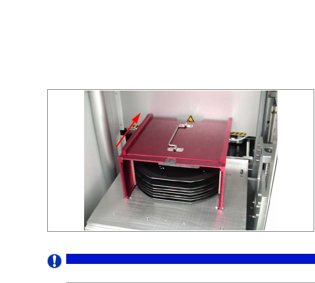
6.4.4 Inserting the Magazine into the Magazine Lift
Open the sliding door of the magazine lift and place the magazine onto the plate. The center-
ing notches of the wafers must face the machine. Make sure that the magazine latches prop-
erly.
Fig. 6.4 - 1 Inserting the magazine
6
PLEASE NOTE
When inserting the wafer frame, the recesses in the wafer frame must point in the feed-
in direction.
6 Working with the Machine User Manual SIPLACE CA-Series
6.4 SWS Tasks From software version SC.708.0 Edition 12/2014 EN -DRAFT
358
6.4.5 Setting up the Needle Configuration for the Ejection System
In the SWS GUI, switch over to the Manual operations -> Wafer handling view and click on
the Go to change position button.
The wafer table is removed.
In the SWS GUI, switch over to the Manual operations -> Die handling view and select the
Ejection unit tab.
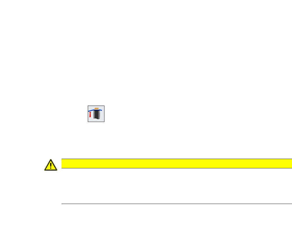
Click on the button.
The wafer table is removed, the die ejector is moved upwards can be accessed.
6
Switch off the placement machine and the SWS properly.
6
Open the protective cover above the SWS.
Open the bayonet lock at the centering unit and take the needle kit out.
CAUTION
Risk of damage!
When moving the wafter table manually, the ejection system which was moved upwards
could collide with the wafer table and be damaged.
Do not push the wafer table manually.
User Manual SIPLACE CA-Series 6 Working with the Machine
From software version SC.708.0 Edition 12/2014 EN -DRAFT 6.4 SWS Tasks
359
6
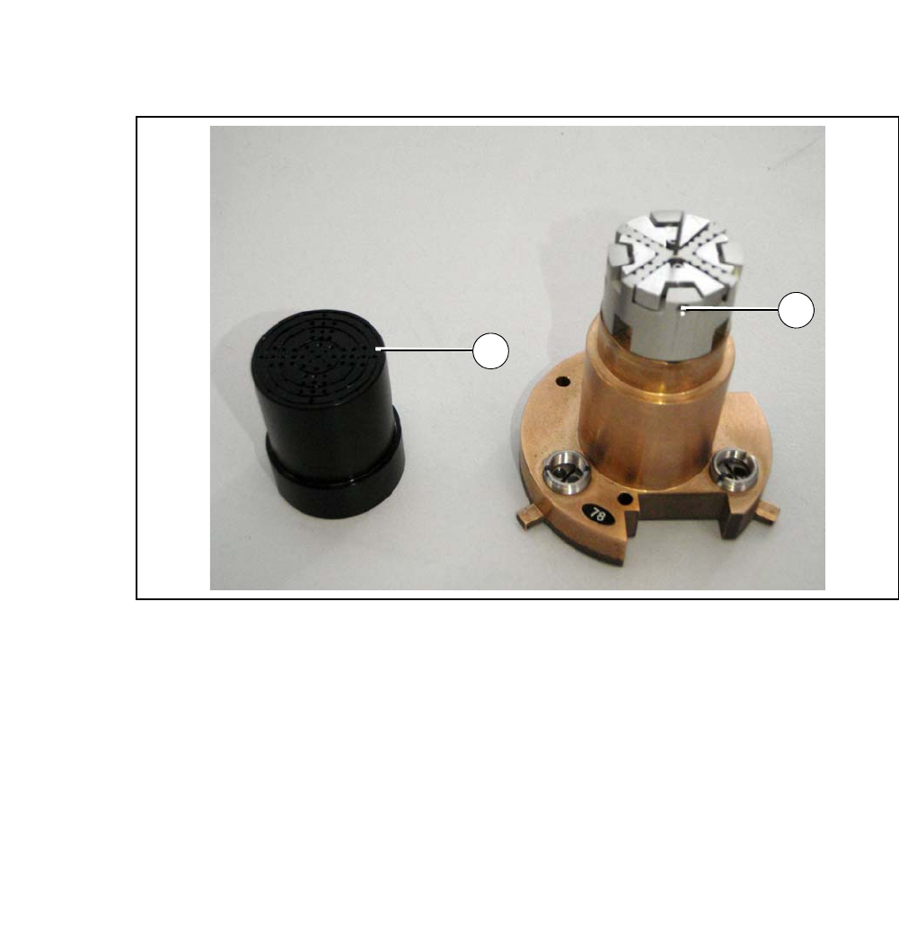
Fig. 6.4 - 2 Needle kit with vacuum cap removed
Legend
6
Remove the vacuum cap from the needle kit (1).
Loosen the grub screw (2).
Insert the appropriate needle matrix for your product.
Insert all needles carefully into the segments and align the needles in about the same line.
Loosely screw in the grub screws. The needles still have to be movable.
Carry out the following adjustments with the relevant calibration standard.
(1) Vacuum cap (2) Grub screw
1
2