00197498-03_UM_SiplaceCA-Serie_EN.pdf - 第363页
User Manual SIPLACE CA-Series 6 Working with the Machine From software version SC.708.0 Edition 12/20 14 EN -DRAFT 6.5 Shift Changeover 363 6.5 Shif t Changeover S plice the tapes early . The feeder modules do no t hav…
6 Working with the Machine User Manual SIPLACE CA-Series
6.4 SWS Tasks From software version SC.708.0 Edition 12/2014 EN -DRAFT
362
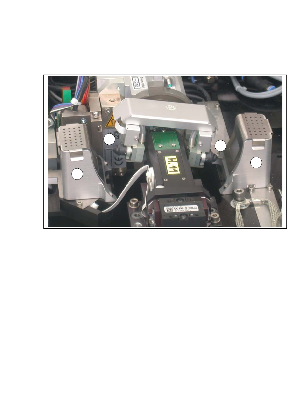
6.4.6 Checking and Configuring the Tools and Nozzles on the Flip Unit
Switch off the placement machine and the SWS properly.
Open the protective cover above the SWS.
6
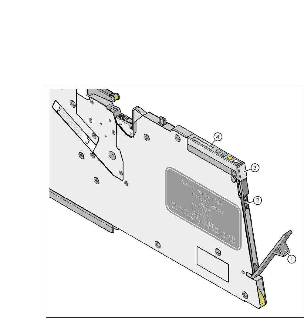
Fig. 6.4 - 5 Flip unit with nozzles and reject bins
Legend
6
Check the state and type of the nozzles and tools on the flip unit. If necessary, replace them
with new ones or those appropriate for the product.
You can either use the standard nozzles of the SIPLACE placement machines or rubber tips
together with an appropriate adapter.
Proceed with checking the reject bins.
6.4.7 Checking the Reject Bin of the Flip Unit
Check and empty the reject bin on the flip unit (item 2 in fig. 6.4 - 5).
When replacing the reject bins make sure that the underlying surface is clean and that the bin
is seated correctly in its fixation. Otherwise they are not recognized by the sensors.
Close the protective cover above the SWS.
Switch the SWS and the placement machine on.
(1) Nozzle segment 1 (2) Nozzle segment 2
(3) Reject bin
2
3
3
1

User Manual SIPLACE CA-Series 6 Working with the Machine
From software version SC.708.0 Edition 12/2014 EN -DRAFT 6.5 Shift Changeover
363
6.5 Shift Changeover
Splice the tapes early. The feeder modules do not have to be refilled as soon as the new shift
starts. This minimizes extended down times.
At the shift change, pass important information on to the next operator. This includes, for in-
stance, changes to the placement program. Also read through the list of the descriptions of
the steps to take in section 6.10
.
Perform a setup check.
Make sure that the feeder modules are equipped with the correct components, that they are
at the correct locations in the component trolley and that the conveyor increment is set cor-
rectly.
SWS:
Check that the tools on the flip head are seated correctly (see section 6.4.6 on page 362) and
then check those on the die attach head, if required. Remove any components from the ma-
chine. Check whether the correct multiple needle kit has been fitted (see section 6.4.5 on
page 358). Remove any flux from the LDU and clean the LDU thoroughly with alcohol, using
the clean cycle. For more details, see the SIPLACE LDU-X User Manual (item number of Ger-
man version [00196057-xx]).
6
PLEASE NOTE
Clean line at transfer
At the end of your shift, transfer the line in the state that you would like to find it in when
you begin your shift, meaning:
– The reject bins (also for SWS) are empty (see section 6.4.7 on page 362).
– The waste tape containers are empty.
– The feeding areas are carefully cleaned with a vacuum cleaner.
6 Working with the Machine User Manual SIPLACE CA-Series
6.6 Performing a Sight Check From software version SC.708.0 Edition 12/2014 EN -DRAFT
364
6.6 Performing a Sight Check
6.6.1 Checking the Feeders (X-Series)
6
Fig. 6.6 - 1 Checking the X feeder modules
(1) Flap
(2) Blade
(3) Status display
(4) LCD display
6
Check to see whether the tape foil removal container for the X tape feeder module is full.
Open the flap (item 1). Pull out the cover foil and cut it with scissors or on the integral blade
(item 2) on 8 and 12 mm X tape feeder modules.