00197498-03_UM_SiplaceCA-Serie_EN.pdf - 第378页
6 Working with the Machine User Manual SIPLACE CA-Series 6.7 Configuring the Feeder Modules From software version SC.708.0 Edition 12/2014 EN -DR AFT 378 6 Fig. 6.7 - 7 Guiding the cover foil to the foil packing wheels (…
User Manual SIPLACE CA-Series 6 Working with the Machine
From software version SC.708.0 Edition 12/2014 EN -DRAFT 6.7 Configuring the Feeder Modules
377
On the operator panel, press the FORWARD button (item 1 in fig. 6.7 - 6) until the bend of
the cover foil is in the component pickup area (item 4 in fig. 6.7 - 5
).
6
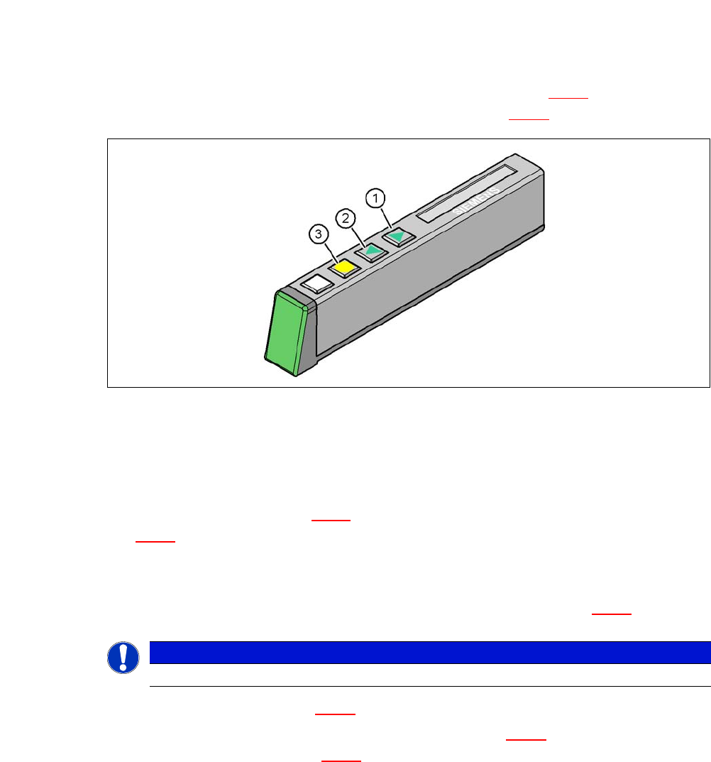
Fig. 6.7 - 6 Operating panel of feeder module
(1) FORWARD button for moving the component tape forward
(2) BACK button for moving the component tape back
(3) FOIL button for tensioning the cover foil
Push the lever (item 5 in fig. 6.7 - 5) forward in order to raise the pickup window (item 2 in fig.
6.7 - 5
) to the first position.
Pull the cover foil at the side of the pick-up window forward and out underneath the pick-up
window.
Fold the cover foil back until it lies against the pull-off edge (item 3 in fig. 6.7 - 5).
6
Push the lever (item 5 in fig. 6.7 - 5) back, to lower the pick-up window.
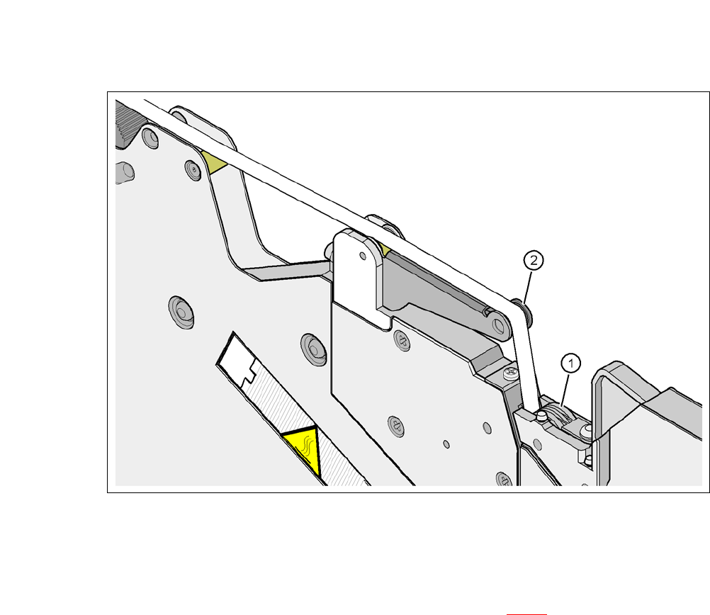
Guide the cover foil over the cover foil rocker (item 2 in fig. 6.7 - 7) until it reaches the foil
packing wheels (item 1 in fig. 6.7 - 7
).
PLEASE NOTE
Do not lower the pick-up window until the cover foil is lying against the pull-off edge.
6 Working with the Machine User Manual SIPLACE CA-Series
6.7 Configuring the Feeder Modules From software version SC.708.0 Edition 12/2014 EN -DRAFT
378
6
Fig. 6.7 - 7 Guiding the cover foil to the foil packing wheels
(1) Cover foil packing wheels
(2) Cover foil
6
On the operator panel, press the FOIL button (item 3 in fig. 6.7 - 6) until the cover foil is ten-
sioned. The cover foil rocker points down and stops the drive motor.
Cut the component tape flush with the front end of the feeder module.
User Manual SIPLACE CA-Series 6 Working with the Machine
From software version SC.708.0 Edition 12/2014 EN -DRAFT 6.8 Setting Up the X Feeder Module
379
6.8 Setting Up the X Feeder Module
The configuration of the X feeder modules is described in the relevant job guide.
6.9 LCD and Status Displays on the X Feeder Module
The X feeder modules have a multicolor status display (item 6) for signaling the operating statuses
and an LCD display (item 1) to display the texts.
– If the status display lights up green, the feeder module is on standby and is contained in
the current setup. If the feeder module is not contained in the current setup, the status
display remains off.
– If the status display lights up orange, it is signaling a warning. The text of the warning
appears on the LCD display.
– If the status display lights up red, a malfunction has occurred. The error message is is-
sued on the LCD display.
6
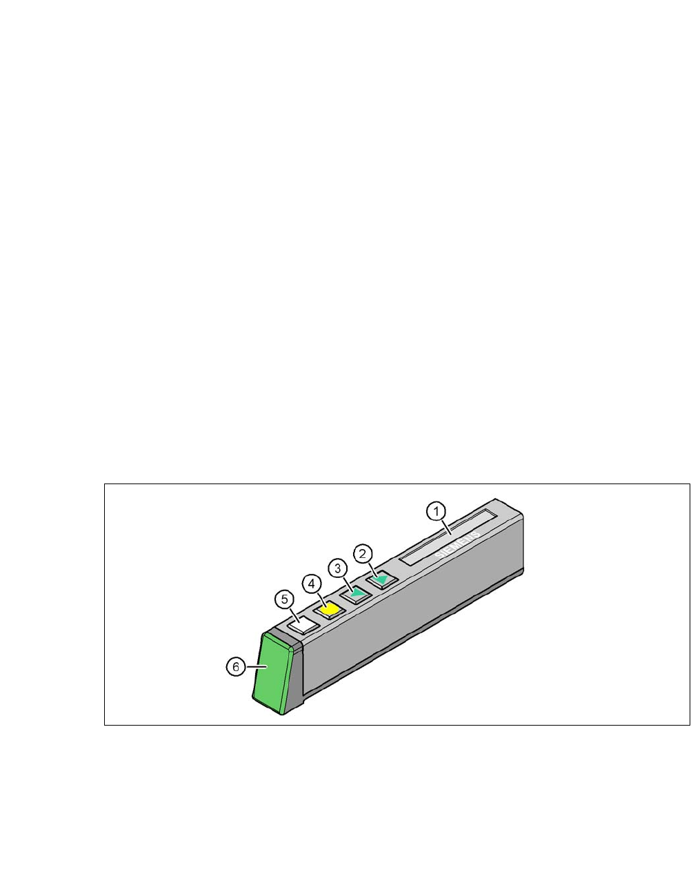
Fig. 6.9 - 1 Buttons, LCD and status displays on the X feeder module
The following tables contain the wording of the LCD display, the color and the mode of the status
display, its meaning and troubleshooting measures.
(1) LCD display (2) FORWARD button
(3) BACK button (4) FOIL button
(5) SET button (6) Status display, multicolor