00197498-03_UM_SiplaceCA-Serie_EN.pdf - 第384页
6 Working with the Machine User Manual SIPLACE CA-Series 6.11 Avoiding Track Errors From software version SC.708.0 Edition 12/2014 EN -DRAFT 384 6.1 1 A voiding T rack Errors 6.1 1.1 General Make sure that the areas ar…

User Manual SIPLACE CA-Series 6 Working with the Machine
From software version SC.708.0 Edition 12/2014 EN -DRAFT 6.10 Changing the Setup
383
6.10.2 Changing the Setup on the SWS
Check whether the orientation of the wafer locking bar matches the relevant wafer size (see
fig. 4.3 - 5
page 221).
6
Adjust the support plate for the wafer magazine and insert the new magazine. check that the
magazine is occupied correctly.
Check the needle configuration of the ejector system (see section 6.4.5, page 358).
Check whether the flip unit has been fitted with the required tools and nozzles (see section
6.4.6, page 362).
Load or compile the required product (see software guide).
PLEASE NOTE
Configuring the SWS
When putting the SWS into operation, it is configured with the required wafer size and
thickness of the wafer frame.
Adapting the SWS to other sizes and thicknesses is described in the service manual.

6 Working with the Machine User Manual SIPLACE CA-Series
6.11 Avoiding Track Errors From software version SC.708.0 Edition 12/2014 EN -DRAFT
384
6.11 Avoiding Track Errors
6.11.1 General
Make sure that the areas around the feeder modules are clean and that there are no loose
components in the feeder area or under the feeder modules.
Refill in good time with components.
Splice the tapes early. This generally means that you are to prepare the splicing material
when there is still approximately 1.5 m of tape on the reel.
Handle the feeder modules carefully when you insert them into or remove them from the
changeover table as these are high-precision devices.
Lower the pickup window for X feeder modules, as this can easily be damaged when raised.
6
Check that the pick-up position is set correctly for the components on the feeder modules.
6
6
6
6
PLEASE NOTE
A raised pick-up window leads to noticeably impaired pick-up quality.
User Manual SIPLACE CA-Series 6 Working with the Machine
From software version SC.708.0 Edition 12/2014 EN -DRAFT 6.11 Avoiding Track Errors
385
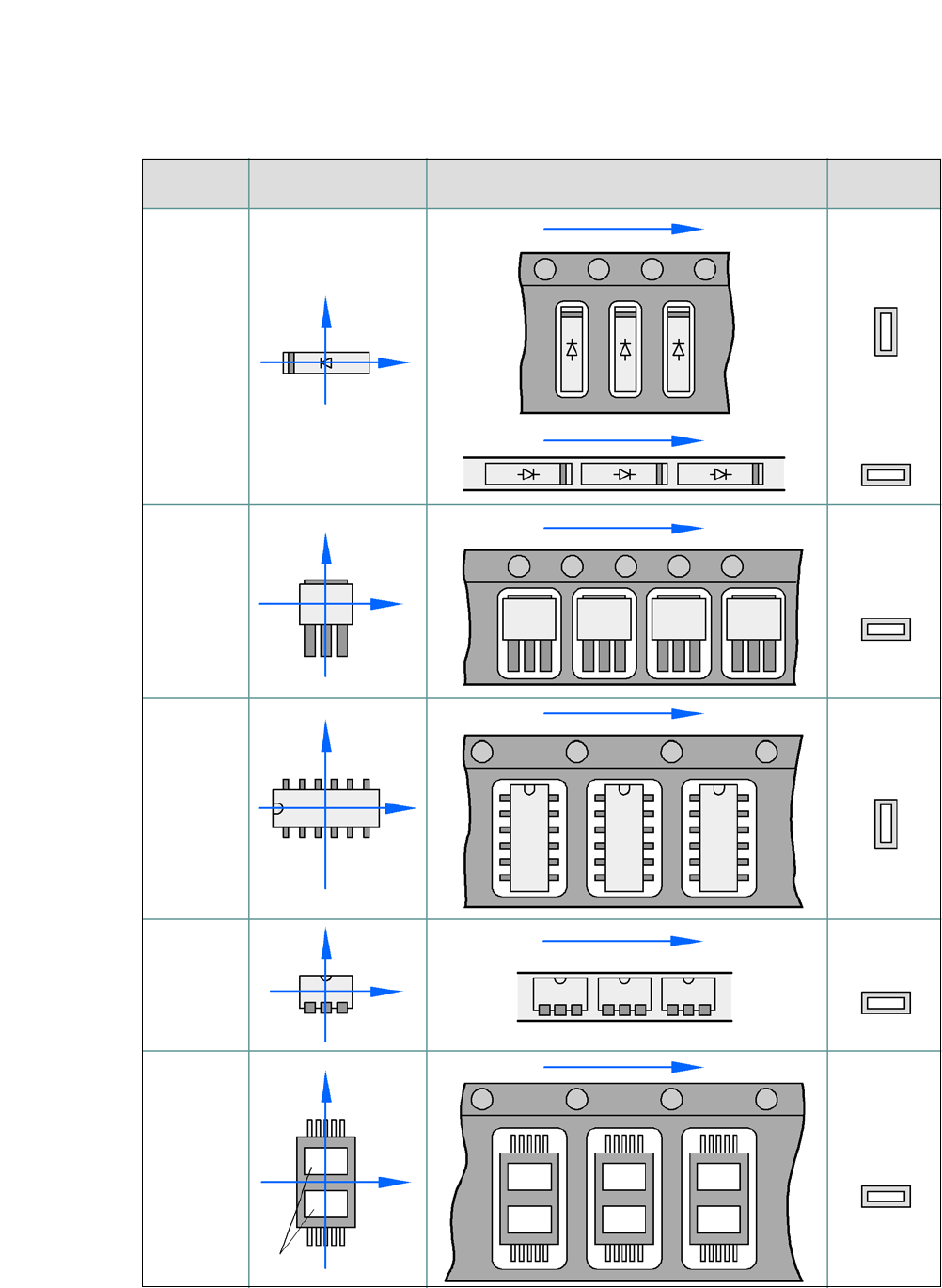
6.11.2 Component Coordinate System and Pickup Angle
6
Fig. 6.11 - 1 Position of the component and its pickup angle
Special
component
Stick
magazine:
Chip-
components
with polarity
0402
2220
The anode must be
aligned with the +X
coordinate.
Package form 0° coordinate system
Position in the feeder module
Pickup angle/
nozzle angle
Tape:
SOT 23
Stick
magazine:
Tape:
Tape:
SO-IC
DIL-IC
SOT 194
Tape:
Holes
Y
X
Y
X
Y
X
Y
X
Y
X
90°
90°
0°
90°
-90°
0°