00197498-03_UM_SiplaceCA-Serie_EN.pdf - 第399页
User Manual SIPLACE CA-Series 7 Component and Die Handling From software version SC.708.0 Edition 12/20 14 EN -DRAFT 7.1 X Feeder Modules for SIPLACE X-Series 399 7.1.1.4 T ape Feeder Module Geometry for the SIPLACE X-Se…

7 Component and Die Handling User Manual SIPLACE CA-Series
7.1 X Feeder Modules for SIPLACE X-Series From software version SC.708.0 Edition 12/2014 EN -DRAFT
398
The overall height of the blister tapes depends on the tape width, and must not exceed the follow-
ing maximum values:
For 8 mm paper tapes, the paper thickness must not exceed 1.6 mm. The length of a component
pocket in the direction of tape travel may not exceed 51 mm.
7.1.1.2 Tape Reel Diameter
The tape reel diameter may be up to 19" (483 mm) for all feeder modules. For a list of the maxi-
mum tape reel diameters, in accordance with the PCB conveyor height, refer to section 7.2.7.2
,
page 434
.
7.1.1.3 Manual Removal of Tantalum Capacitors That Were Not Picked Up By The
Operator
To prevent tantalum capacitors which were not picked up from causing the tape material to burn
when it is cut, the user interface has been extended to include the option "Stop immediately on
pickup error". This option must be enabled in SIPLACE Pro. On the placement machine, the com-
ponent that was not picked up is paced forward again until it is ready for removal from the com-
ponent tape. The track is deactivated and the operator is sent an error message to remind him to
pick up the tantalum component from the tape. If an alternative track is available, the machine con-
tinues placing. The operator is able to stop the machine, however, and pick up the tantalum com-
ponent. If no alternative track is available and it is not possible to continue placement with other
components, the machine will stop. At this point, the operator can again remove the tantalum com-
ponent and acknowledge the error. Once the operator has restarted the machine, placement is
continued and components are picked up from the track that is now enabled once more.
7
Tape width Overall height of the blister tapes
4 mm Max. 1.1 mm
8 mm Max. 3.5 mm
12 mm Max. 6.5 mm
16 mm and wider Max. 25 mm
PLEASE NOTE
This software function is also a good idea for expensive components.
Please observe the safety instructions for capacitors on metallic powder basis (see section 2.6.2,
page 71
).

User Manual SIPLACE CA-Series 7 Component and Die Handling
From software version SC.708.0 Edition 12/2014 EN -DRAFT 7.1 X Feeder Modules for SIPLACE X-Series
399
7.1.1.4 Tape Feeder Module Geometry for the SIPLACE X-Series
In general, the tape feeder modules from the X-Series are approx. 587 mm long and approx. 200
mm high. The width and the number of locations that it fills on the changeover table are listed in
the following table.
7
The maximum height of the interference contours above the upper edge of the tape pocket is ≤ 3
mm. As the feeder modules do not show any flaps projecting upwards and are also fixed to the
changeover tables, the risk of a head crash is reduced to a minimum.
Tape feeder
modules
Feeder module width in
millimeters
Feeder module locations
occupied on the changeover
table
4 mm 10.8 1
2x8 mm X 22.6 2
8 mm X 10.8 1
Smart Feeder 12 mm X 22.6 2
Smart Feeder 16 mm X 22.6 2
24 mm X 34.4 3
32 mm X 46.2 4
44 mm X 58.0 5
56 mm X 69.8 6
72 mm X 81.6 7
88 mm X 105.2 9
7 Component and Die Handling User Manual SIPLACE CA-Series
7.1 X Feeder Modules for SIPLACE X-Series From software version SC.708.0 Edition 12/2014 EN -DRAFT
400
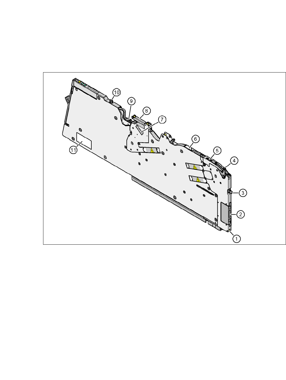
7.1.1.5 Design of Tape Feeder Module for SIPLACE X-Series
The two following diagrams show the design of the tape feeder module for the X-Series with ref-
erence to the 8 mm X tape feeder module.
7
Fig. 7.1 - 1 Tape feeder module 8 mm X - front view
(1) Locking roller (the locking latch of the changeover table locks the feeder module in its end
position with the locking roller.)
(2) EDIF (energy and data interface)
(3) "Front" centering pin
(4) Lever for raising the pick-up window in order to thread in and remove the component tape
(5) Pickup window
(6) Tape guide channel outlet
(7) Setting the cover foil tension
(8) Cover foil rocker
(9) Cover foil packing wheels
(10) "Back" centering pin
(11) Type plate