00197498-03_UM_SiplaceCA-Serie_EN.pdf - 第401页
User Manual SIPLACE CA-Series 7 Component and Die Handling From software version SC.708.0 Edition 12/20 14 EN -DRAFT 7.1 X Feeder Modules for SIPLACE X-Series 401 7 Fig. 7.1 - 2 T ape feeder module 8 mm X - back vie w (1…
7 Component and Die Handling User Manual SIPLACE CA-Series
7.1 X Feeder Modules for SIPLACE X-Series From software version SC.708.0 Edition 12/2014 EN -DRAFT
400
7.1.1.5 Design of Tape Feeder Module for SIPLACE X-Series
The two following diagrams show the design of the tape feeder module for the X-Series with ref-
erence to the 8 mm X tape feeder module.
7
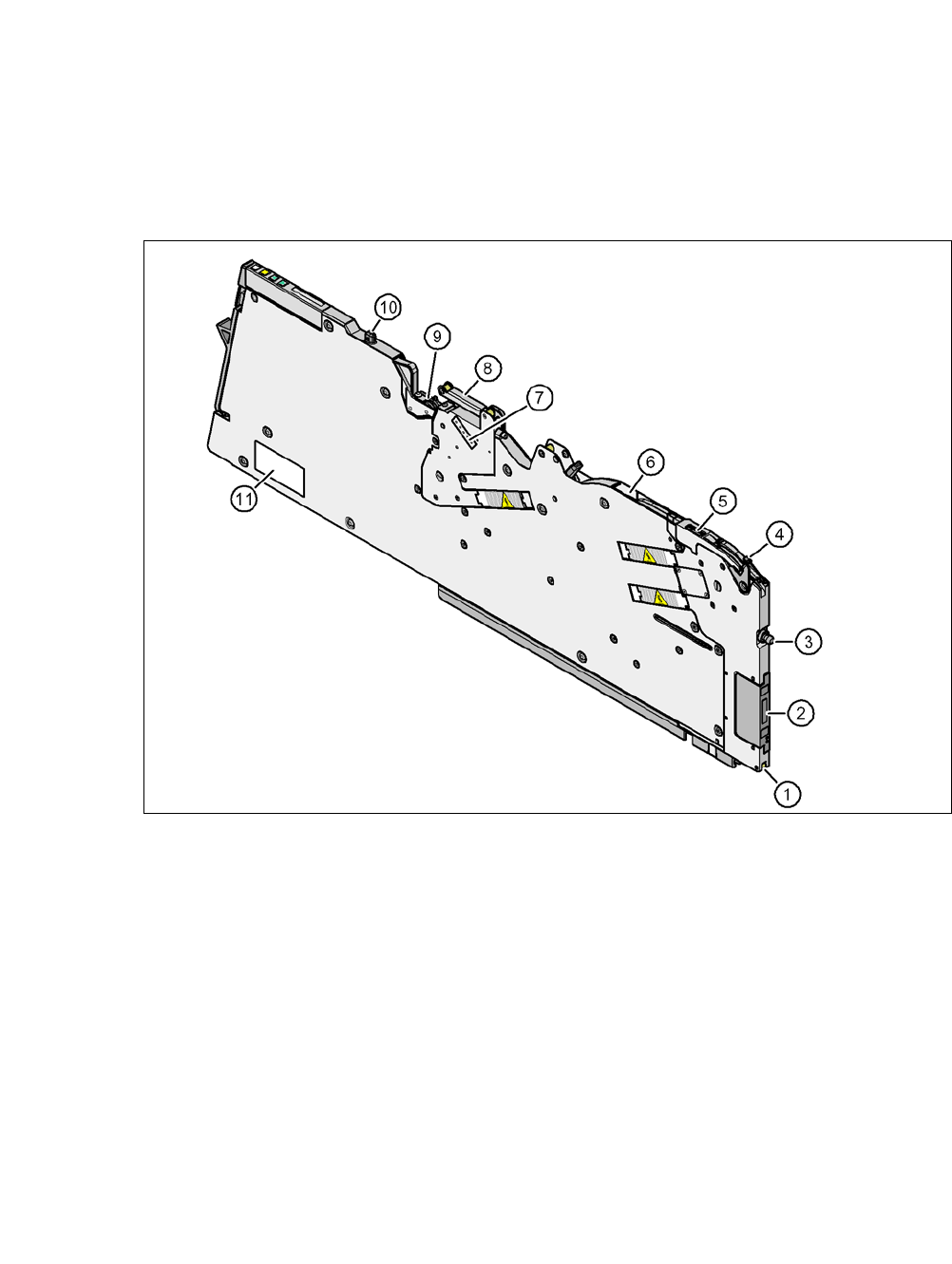
Fig. 7.1 - 1 Tape feeder module 8 mm X - front view
(1) Locking roller (the locking latch of the changeover table locks the feeder module in its end
position with the locking roller.)
(2) EDIF (energy and data interface)
(3) "Front" centering pin
(4) Lever for raising the pick-up window in order to thread in and remove the component tape
(5) Pickup window
(6) Tape guide channel outlet
(7) Setting the cover foil tension
(8) Cover foil rocker
(9) Cover foil packing wheels
(10) "Back" centering pin
(11) Type plate
User Manual SIPLACE CA-Series 7 Component and Die Handling
From software version SC.708.0 Edition 12/2014 EN -DRAFT 7.1 X Feeder Modules for SIPLACE X-Series
401
7
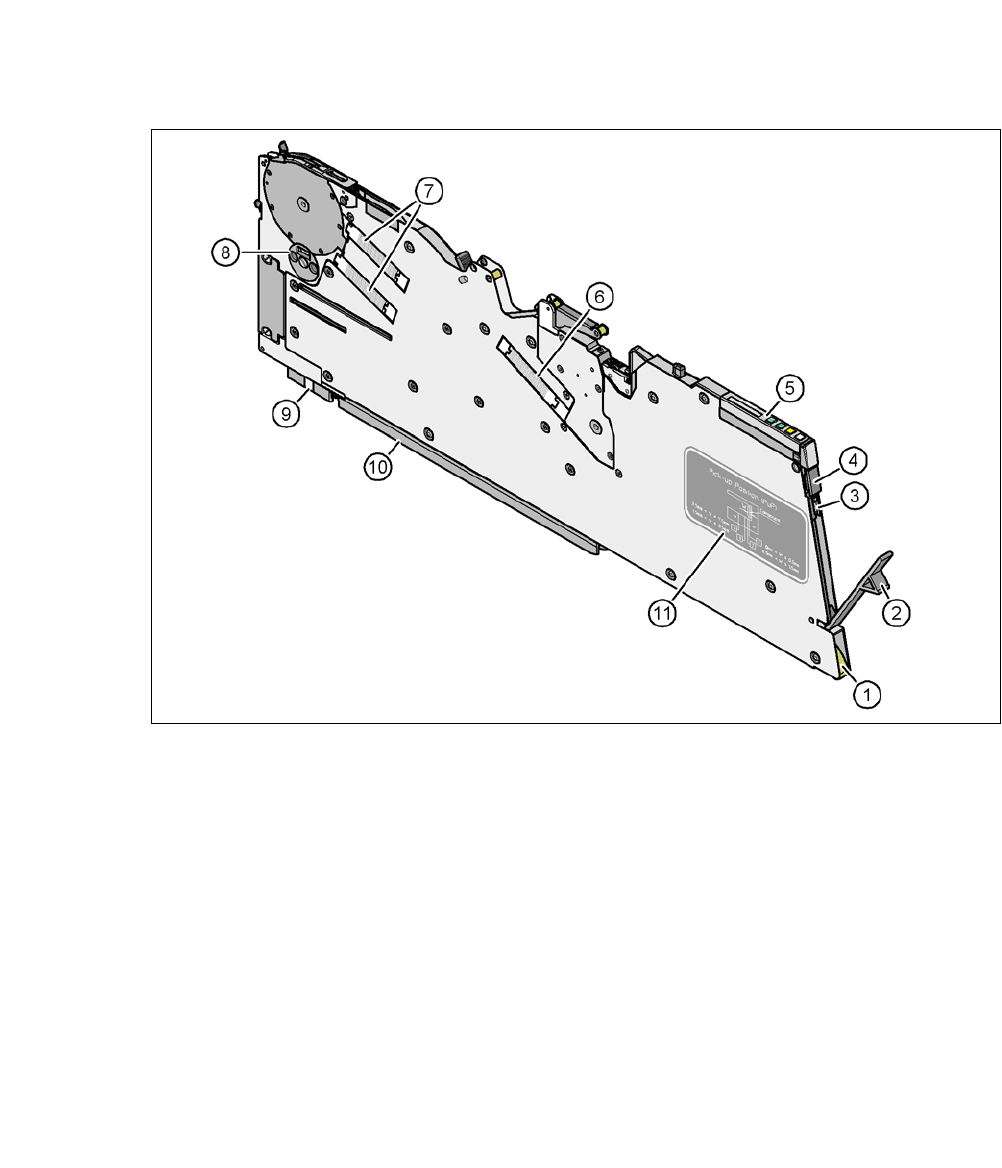
Fig. 7.1 - 2 Tape feeder module 8 mm X - back view
(1) Entry to the tape guide channel with tape spring
(2) Flap on cover foil container
(3) Integrated blade for cutting off the cover foil
(4) Removal handle, engaged
(5) Operator panel
(6) Drive motor for the cover foil packing device
(7) Drive motors for the tape conveyor
(8) Rotary valve for removing components
(9) Front slider guide
(10) Back slider guide
(11) Graphical representation of the pick-up position in relation to the component size
7 Component and Die Handling User Manual SIPLACE CA-Series
7.1 X Feeder Modules for SIPLACE X-Series From software version SC.708.0 Edition 12/2014 EN -DRAFT
402
7.1.2 Technical Data for the SIPLACE X-Series Feeder Modules
The following pages contain pictures of the X-Series feeder modules and the technical data.
7.1.2.1 Tape Feeder Module 4 mm X
7
Fig. 7.1 - 3 Tape Feeder Module 4 mm X
7
Tape Feeder Module 4 mm X Item no. 00141268-xx
Width 10.8 mm
Feeder module locations filled 1
Conveyor increment 1 mm
Changeover time for the component tape < 45 s
Changeover time for the preset feeder module
on the machine
≤ 8 s