00197498-03_UM_SiplaceCA-Serie_EN.pdf - 第416页
7 Component and Die Handling User Manual SIPLACE CA-Series 7.1 X Feeder Modules for SIPLACE X-Series From software version SC.708.0 Edition 12/2014 EN -DRAFT 416 7.1.4.1 Description The Linear Dipping Unit X (linear dip …
User Manual SIPLACE CA-Series 7 Component and Die Handling
From software version SC.708.0 Edition 12/2014 EN -DRAFT 7.1 X Feeder Modules for SIPLACE X-Series
415
7.1.4 Linear Dipping Unit X (LDU X)
Item no. 00117011-xx Linear dip module for flux / LDU-X
Item no. Dip plates see section 7.1.4.4
, page 417
7
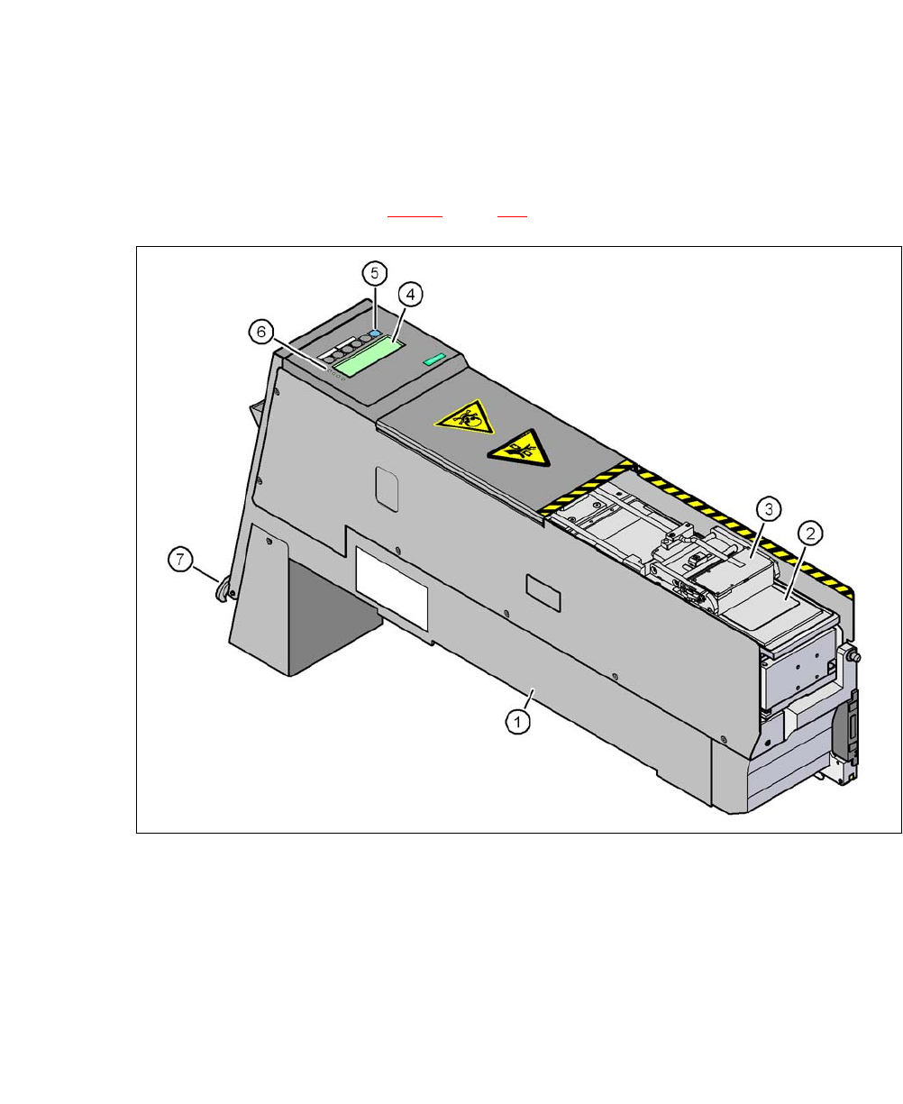
Fig. 7.1 - 15 Linear Dipping Unit (LDU X)
(1) LDU X
(2) Dip plate
(3) Flux container
(4) Display panel (4 lines each with 20 characters)
(5) Operator panel with 6 membrane keys
(6) LED for status displays
(7) EMERGENCY OFF button

7 Component and Die Handling User Manual SIPLACE CA-Series
7.1 X Feeder Modules for SIPLACE X-Series From software version SC.708.0 Edition 12/2014 EN -DRAFT
416
7.1.4.1 Description
The Linear Dipping Unit X (linear dipping unit X, item 1 in fig. 7.1 - 15) is used for coating Flip-
Chips and CSP components with flux. The flux container (item 3 in fig. 7.1 - 15
) slides with a linear
movement over the dip plate (item 2 in fig. 7.1 - 15
) and coats the cavity in the dip plate with a
layer of flux (predefined layer thickness). The parameters for coating a component with flux are
prescribed in SIPLACE Pro. The component is coated and then the flux layer is renewed. This
sequence guarantees consistent processing conditions for the components.
The display field (item 4 in fig. 7.1 - 15
, page 415) shows the individual menus for actions and op-
erating parameters. The buttons on the operator panel (item 5 in fig. 7.1 - 15
, page 415) allow you
to select menus, edit and save parameters. The 4 LEDs (item 6 in fig. 7.1 - 15
, page 415) on the
display field signal the status of the LDU-X. The EMERGENCY STOP button (item 7 in fig. 7.1 -
15, page 415) immediately switches the LDU-X off.
The LDU-X is taken into account as an independent feeder module type in the setup. This module
can be set up on the component trolley of the SIPLACE X-Series. An implemented warming func-
tion allows the viscosity of the flux to be altered. For test purposes, the LDU-X can be operated
outside the machine with the energy and data interface for X feeder modules (see section 7.1.6
,
page 422
).
7.1.4.2 Technical Data
Further technical data and details can be found in the "SIPLACE LDU-X" user manual.
Occupies 8mm locations on the component trolley
of SIPLACE X-Series.
9
Component size Max. 55 mm x 55 mm, depending on place-
ment head type
The adjustable flux layer thickness 15 - 260 μm
Tolerance of the layer thicknesses ± 5 μm ... ± 10 µm
Time for applying the flux to the dip plate > 3s
Component dipping time adjustable using the software
Flux Indium TACFlux 010 / 013
Kester TSF-6502 / 6522
Alphametals OM338 / OM338PT
Almit BM1 RMA
Cookson WS 3018lv
etc.
Placement heads which can be used MultiStar, SpeedStar, TwinStar

User Manual SIPLACE CA-Series 7 Component and Die Handling
From software version SC.708.0 Edition 12/2014 EN -DRAFT 7.1 X Feeder Modules for SIPLACE X-Series
417
7.1.4.3 Restrictions
– The LDU-X must be manually configured in the setup.
– The LDU-X may only be set up on tracks 7 – 26.
– You can only configure one LDU-X per component trolley.
– Linear vibratory feeders may not be set up directly next to a LDU-X.
– MTC or WPC and LDU-X may only be set up in one placement area with one gantry.
– A gantry can only pick up from one LDU-X, even if it can pick up from two placement locations.
7.1.4.4 Dip Plates for Specified Flux Layer Thicknesses
Dip plate depth Item no.
30 μm 00117023-xx
60 μm 00117026-xx
70 μm 00117027-xx
75 μm 00117021-xx
80 μm 00117028-xx
90 μm 00117029-xx
100 μm 00117030-xx
110 μm 00117038-xx
120 μm 00117031-xx
130 μm 00117039-xx
170 μm 00117054-xx
210 μm 00117042-xx
220 μm 00117032-xx
230 μm 00117033-xx
240 μm 00117037-xx
280 μm 00117034-xx
300 μm 00117041-xx
320 μm 00117035-xx
360 μm 00117036-xx
400 μm 00117040-xx