00197498-03_UM_SiplaceCA-Serie_EN.pdf - 第425页
User Manual SIPLACE CA-Series 7 Component and Die Handling From software version SC.708.0 Edition 12/20 14 EN -DRAFT 7.2 SIPLACE X-Series Component Trolley 425 The component trolleys are stand-alone modu les that can be …
7 Component and Die Handling User Manual SIPLACE CA-Series
7.2 SIPLACE X-Series Component Trolley From software version SC.708.0 Edition 12/2014 EN -DRAFT
424
7.2 SIPLACE X-Series Component Trolley
[00119722-xx] Component trolley for SIPLACE X-Series
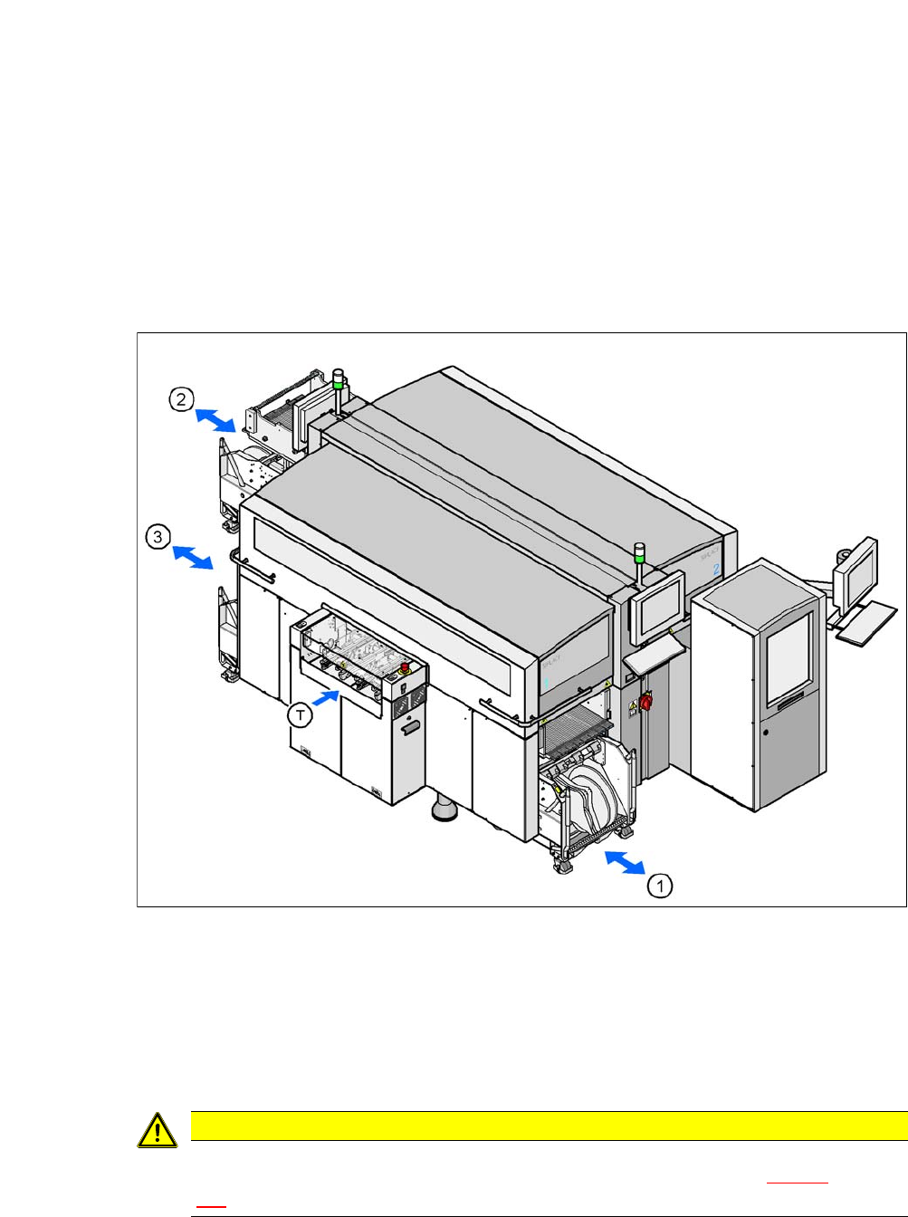
Up to three SIPLACE X-Series component trolleys can be docked onto the SIPLACE CA-Series
machines. The locations are numbered. The following diagram shows the CA4 with an SWS at
location 2 as an example.
7
Fig. 7.2 - 1 Component trolley locations, SIPLACE X-Series - example of SWS at location 2
(1) Location 1
(2) Location 3
(3) Location 4
(T) PCB direction of travel
7
CAUTION
The component trolleys for the SIPLACE SX1/SX2 may only be docked onto locations at
which the COT insert for the SIPLACE SX1/SX2 has been installed fig. 6.14 - 3
, page
389
).
User Manual SIPLACE CA-Series 7 Component and Die Handling
From software version SC.708.0 Edition 12/2014 EN -DRAFT 7.2 SIPLACE X-Series Component Trolley
425
The component trolleys are stand-alone modules that can be set up with feeders at an external
setup area. This means that the production process only has to be interrupted briefly in order to
change the component trolley.
7
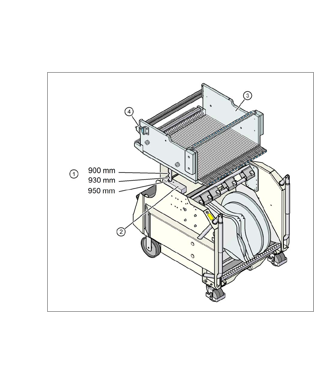
Fig. 7.2 - 2 Component trolley, SIPLACE X-Series, with a PCB conveyor height of 950 mm
7
(1) Holes in the guide columns for the PCB transport heights of 900, 930 and 950 mm.
(2) Support block
(3) Changeover table
(4) Contact for switching the safety switch in the COT insert
7 Component and Die Handling User Manual SIPLACE CA-Series
7.2 SIPLACE X-Series Component Trolley From software version SC.708.0 Edition 12/2014 EN -DRAFT
426
7.2.1 Structure of SIPLACE X-Series Component Trolley
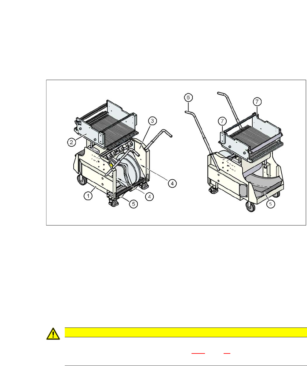
The component trolley essentially consists of the chassis, the changeover table for holding the
feeder modules, the tape reel container and the waste tape container.
7
Fig. 7.2 - 3 Component trolley, SIPLACE X-Series, front and rear view
(1) Chassis
(2) Changeover table
(3) Tape container
(4) Gap for accommodation of setup lists
(5) Waste tape container
(6) Handle
(7) Hand guard
7
CAUTION
Observe the safety instructions!
Observe the safety instructions in section 2.6.8, page 76, when you pull the tape re-
ject bin out of the component trolley.