00197498-03_UM_SiplaceCA-Serie_EN.pdf - 第427页
User Manual SIPLACE CA-Series 7 Component and Die Handling From software version SC.708.0 Edition 12/20 14 EN -DRAFT 7.2 SIPLACE X-Series Component Trolley 427 Assemblies 7 In the standar d version, the t ape reel cont a…
7 Component and Die Handling User Manual SIPLACE CA-Series
7.2 SIPLACE X-Series Component Trolley From software version SC.708.0 Edition 12/2014 EN -DRAFT
426
7.2.1 Structure of SIPLACE X-Series Component Trolley
The component trolley essentially consists of the chassis, the changeover table for holding the
feeder modules, the tape reel container and the waste tape container.
7
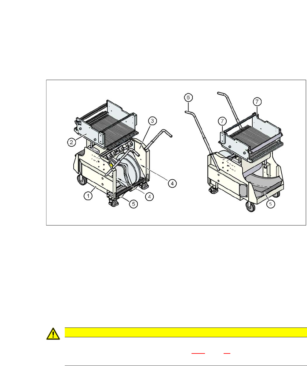
Fig. 7.2 - 3 Component trolley, SIPLACE X-Series, front and rear view
(1) Chassis
(2) Changeover table
(3) Tape container
(4) Gap for accommodation of setup lists
(5) Waste tape container
(6) Handle
(7) Hand guard
7
CAUTION
Observe the safety instructions!
Observe the safety instructions in section 2.6.8, page 76, when you pull the tape re-
ject bin out of the component trolley.
User Manual SIPLACE CA-Series 7 Component and Die Handling
From software version SC.708.0 Edition 12/2014 EN -DRAFT 7.2 SIPLACE X-Series Component Trolley
427
Assemblies 7
In the standard version, the tape reel container (item 3 in fig. 7.2 - 3) holds tape reels up to a size
of 17" (432 mm).
There are two 5 mm wide gaps on the left and right, between the tape container and the compo-
nent trolley (item. 4 in fig. 7.2 - 3
) for storing setup lists.
The pullout waste tape container can be found beneath the chassis (item 5 in fig. 7.2 - 3
). The cut
waste tape travel down a chute into the waste tape container, which must be emptied as it fills up.
The handles (item 6 in fig. 7.2 - 3
) can be folded up or down.
7
7.2.2 Technical Data for the SIPLACE X-Series Component Trolley
7
7
PLEASE NOTE
Operational safety
All component trolleys or matrix tray changers must be docked on the machine in order to
operate it.
Fill any free locations with dummy feeder modules as described in
section 2.8.5
, page 98.
Length x width 727 mm x 592 mm
752 mm x 592 mm with reject bin
Height of the changeover table 889.5 mm for 900 mm PCB conveyor height
919.5 mm for 930 mm PCB conveyor height
939.5 mm for 950 mm PCB conveyor height
PCB conveyor height 900 mm ± 15 mm (option)
930 mm ± 15 mm (standard)
950 mm ± 15 mm (SMEMA option)
Height of handles when folded out 969 mm
Number of locations 40 (8 mm X tape feeder module)
Weight
Without feeder modules
With feeder module at all locations
80.4 kg
139.6 kg
Reel diameter
Standard
Maximum
Up to 432 mm (17")
483 mm (19")
7 Component and Die Handling User Manual SIPLACE CA-Series
7.2 SIPLACE X-Series Component Trolley From software version SC.708.0 Edition 12/2014 EN -DRAFT
428
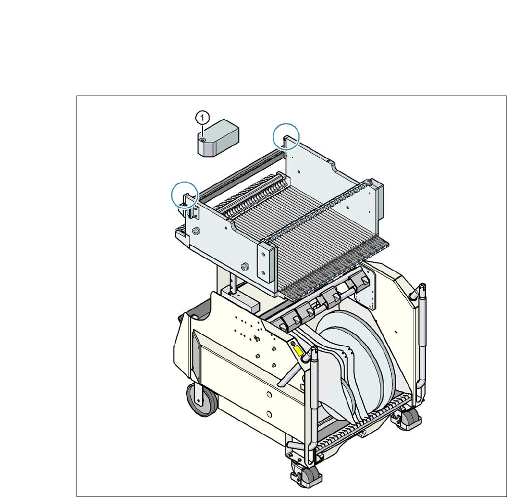
7.2.3 Fiducials on the SIPLACE X-Series Component Trolley
7
Fig. 7.2 - 4 Fiducials on the SIPLACE X-Series Component Trolley
(1) Fiducials on the component trolley
Once the SIPLACE X-Series component trolley has been docked in, the machine measures the
fiducials on the component trolley.
For components with an edge length of less than 0.5 mm, i.e. 0402 components and smaller, the
position of the component is determined with the tape pocket before the first component is picked
up.