00197498-03_UM_SiplaceCA-Serie_EN.pdf - 第429页
User Manual SIPLACE CA-Series 7 Component and Die Handling From software version SC.708.0 Edition 12/20 14 EN -DRAFT 7.2 SIPLACE X-Series Component Trolley 429 7.2.4 Dimensions of SIPLACE X-Series Component T rolley 7 Fi…
7 Component and Die Handling User Manual SIPLACE CA-Series
7.2 SIPLACE X-Series Component Trolley From software version SC.708.0 Edition 12/2014 EN -DRAFT
428
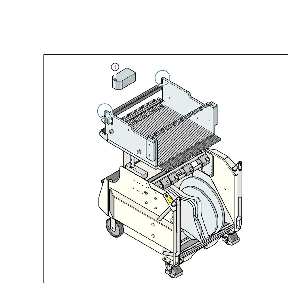
7.2.3 Fiducials on the SIPLACE X-Series Component Trolley
7
Fig. 7.2 - 4 Fiducials on the SIPLACE X-Series Component Trolley
(1) Fiducials on the component trolley
Once the SIPLACE X-Series component trolley has been docked in, the machine measures the
fiducials on the component trolley.
For components with an edge length of less than 0.5 mm, i.e. 0402 components and smaller, the
position of the component is determined with the tape pocket before the first component is picked
up.
User Manual SIPLACE CA-Series 7 Component and Die Handling
From software version SC.708.0 Edition 12/2014 EN -DRAFT 7.2 SIPLACE X-Series Component Trolley
429
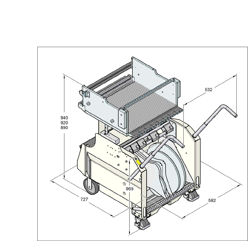
7.2.4 Dimensions of SIPLACE X-Series Component Trolley
7
Fig. 7.2 - 5 Dimensions of the SIPLACE X-Series component trolley; all dimensions in millimeters
7 Component and Die Handling User Manual SIPLACE CA-Series
7.2 SIPLACE X-Series Component Trolley From software version SC.708.0 Edition 12/2014 EN -DRAFT
430
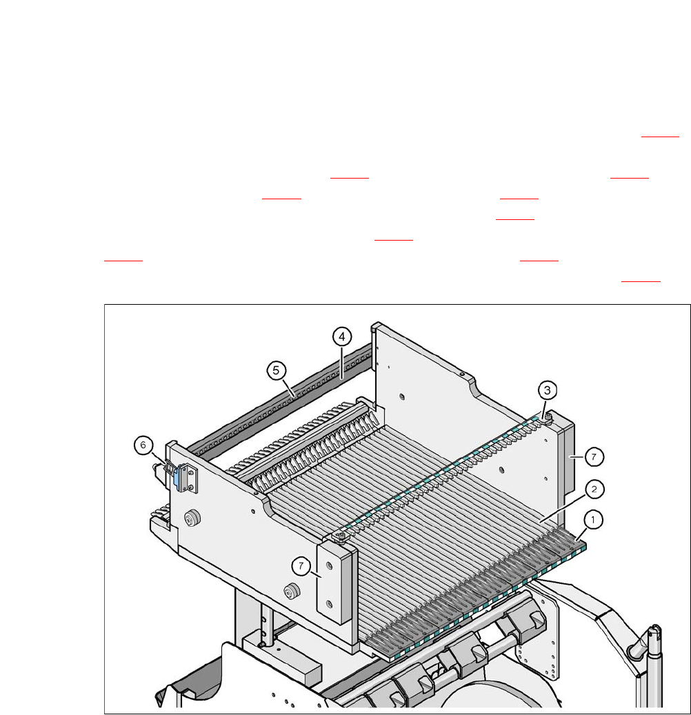
7.2.5 SIPLACE X-Series Changeover Table
The front slider guides of the feeder modules are placed on the insertion aid (item 1 in fig. 7.2 - 6).
When pushed in, the slider guides of the
feeder module (item 12 and 13 in fig. 7.1 - 2
) slide on the guide profile (item 2 in fig. 7.2 - 6) up to
the stop rail (item 4 in fig. 7.2 - 6
). A centering hole (item 5 in fig. 7.2 - 6) on the stop rail accom-
modates the X feeder module centering pin "front" (item 4 in fig. 7.1 - 1
). At the same time, the
changeover table locking latch (item 1 in fig. 7.2 - 7
) engages with the locking roller (item 1 in fig.
7.1 - 1
) of the feeder module. The centering pin "rear" (item 12 in fig. 7.1 - 1) on the upper side of
the feeder module is accommodated by the recess in the centering bar (item 3 in fig. 7.2 - 6
).
7
Fig. 7.2 - 6 Changeover table, SIPLACE X-Series, rear view
(1) Insertion aid
(2) Guide profile (Ω profile)
(3) Centering bar for holding the "back" centering pin for X feeder modules
(4) Stop bar
(5) Centering holes
(6) Contact for switching the safety switch of the EMERGENCY STOP circuit
(7) Hand guard