00197498-03_UM_SiplaceCA-Serie_EN.pdf - 第441页
User Manual SIPLACE CA-Series 7 Component and Die Handling From software version SC.708.0 Edition 12/20 14 EN -DRAFT 7.5 Docking Station for the SIPLACE X-Series Component Trolley 441 7.5.4 Dimensions of Docking St ation…
7 Component and Die Handling User Manual SIPLACE CA-Series
7.5 Docking Station for the SIPLACE X-Series Component Trolley From software version SC.708.0 Edition 12/2014 EN -DRAFT
440
7
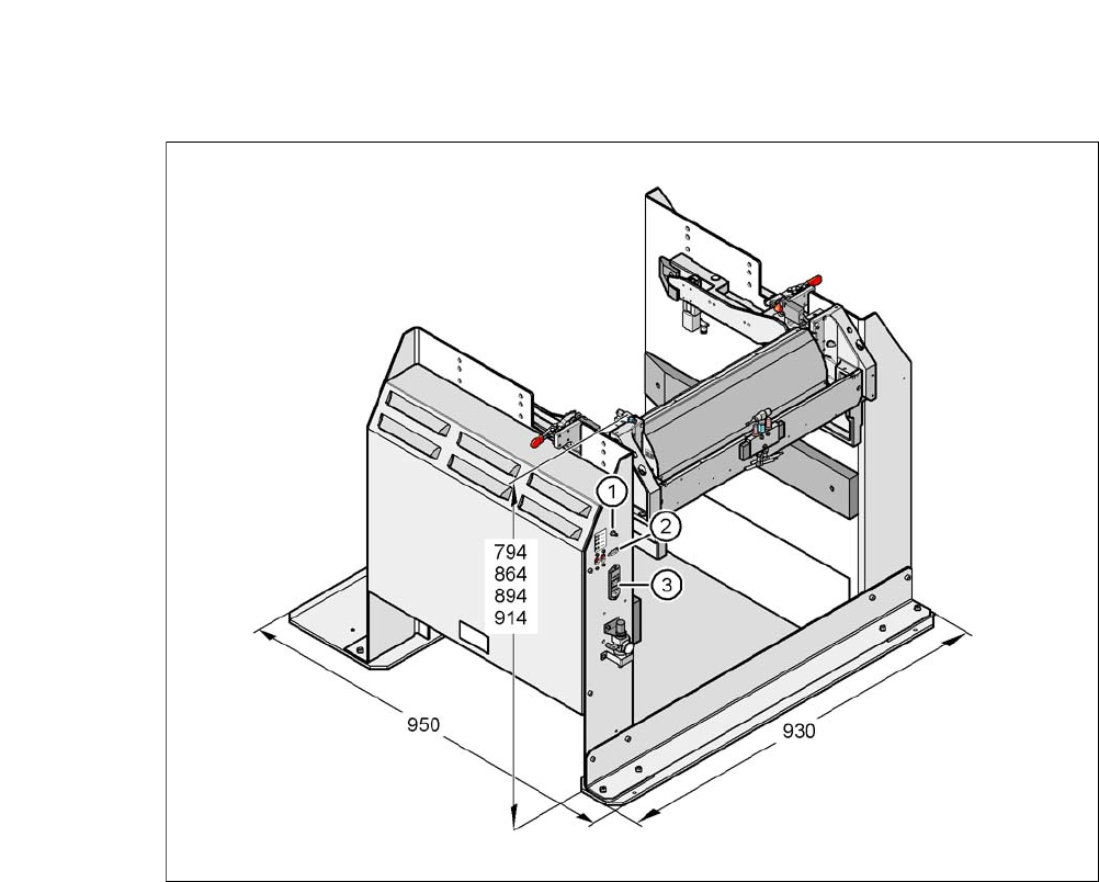
Fig. 7.5 - 2 Docking station - dimensions in millimeters, connection points
(1) Compressed air connection
(2) CAN bus connection
(3) Power supply connection
User Manual SIPLACE CA-Series 7 Component and Die Handling
From software version SC.708.0 Edition 12/2014 EN -DRAFT 7.5 Docking Station for the SIPLACE X-Series Component Trolley
441
7.5.4 Dimensions of Docking Station with Docked Component Trolley
7
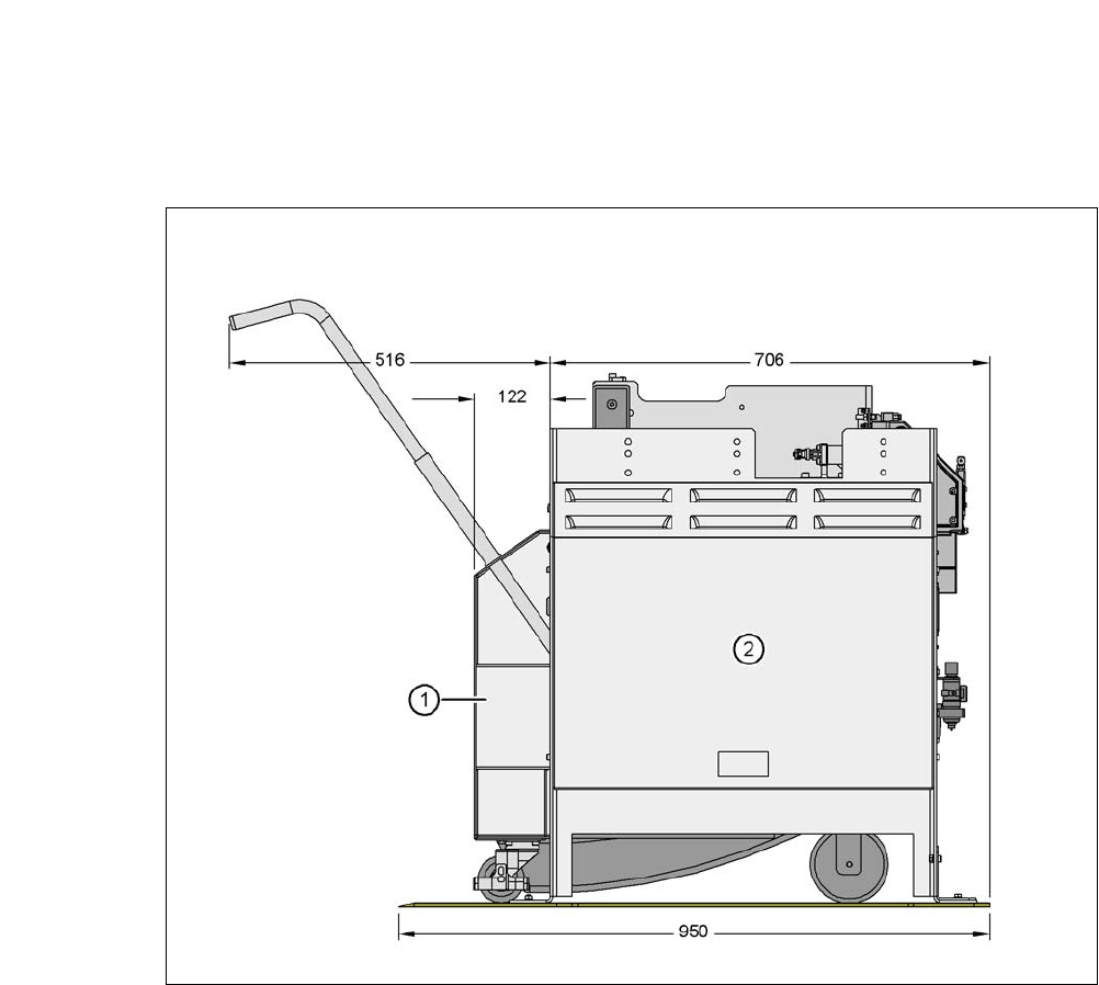
Fig. 7.5 - 3 Docking station with docked component trolley - dimensions in millimeters
(1) Component trolley
(2) Docking station
7 Component and Die Handling User Manual SIPLACE CA-Series
7.5 Docking Station for the SIPLACE X-Series Component Trolley From software version SC.708.0 Edition 12/2014 EN -DRAFT
442
7.5.5 Adjusting the Docking Station to the PCB Conveyor Height
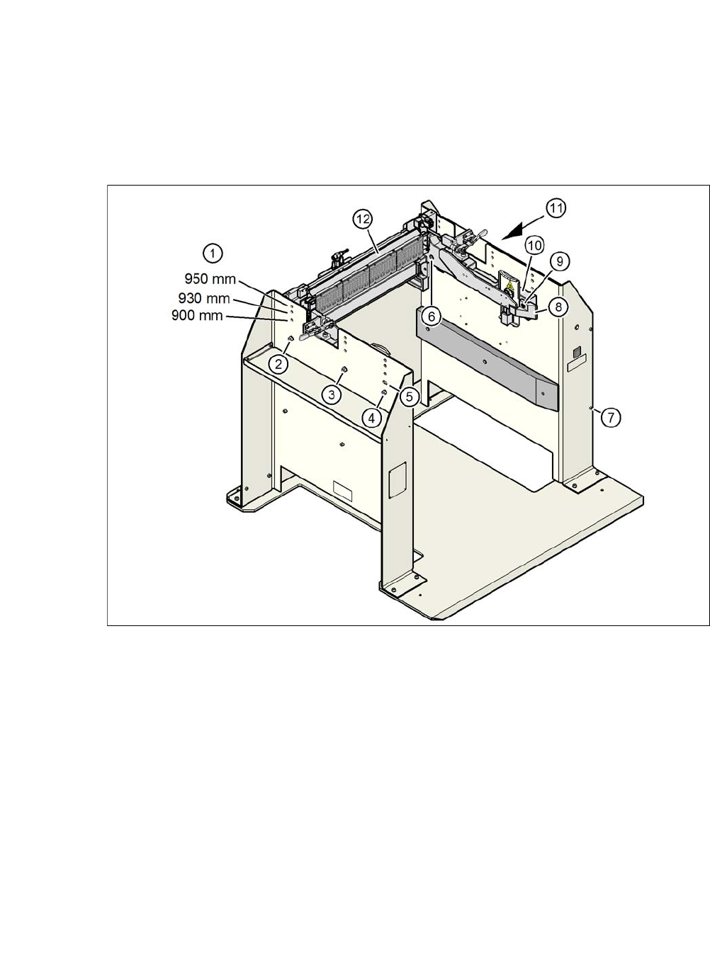
The COT insert for the docking station can be easily converted to PCB conveyor heights of 900,
930 or 950 mm.
7
Fig. 7.5 - 4 Adjusting the docking station to the PCB conveyor height
(1) Holes for the PCB conveyor height
(2) Hexagonal nut M8 and washer, 2x each
(3) Hexagonal nut M8 and washer, 2x each
(4) Hexagonal nut M8 and washer, 2x each
(5) Slot for height adjustment
(6) Hexagon socket-head screw M8x40, 6x
(7) Hexagon socket-head screw M5x12, 4
(8) Guidance
(9) Hexagon socket-head screw M8x18, 2x
(10) Side panel, COT insert
(11) Docking station outer cover
(12) Feeder module control unit (FCU)