00197498-03_UM_SiplaceCA-Serie_EN.pdf - 第442页
7 Component and Die Handling User Manual SIPLACE CA-Series 7.5 Docking Station for the SIPLACE X-Series Component Tr olley From software version SC.708.0 Edition 12/2014 EN -DRAFT 442 7.5.5 Adjusting the Docking St atio …
User Manual SIPLACE CA-Series 7 Component and Die Handling
From software version SC.708.0 Edition 12/2014 EN -DRAFT 7.5 Docking Station for the SIPLACE X-Series Component Trolley
441
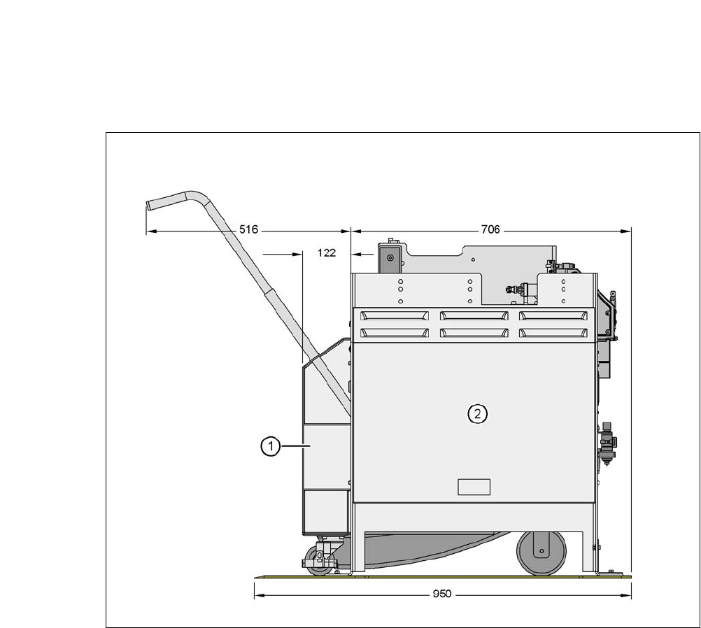
7.5.4 Dimensions of Docking Station with Docked Component Trolley
7
Fig. 7.5 - 3 Docking station with docked component trolley - dimensions in millimeters
(1) Component trolley
(2) Docking station
7 Component and Die Handling User Manual SIPLACE CA-Series
7.5 Docking Station for the SIPLACE X-Series Component Trolley From software version SC.708.0 Edition 12/2014 EN -DRAFT
442
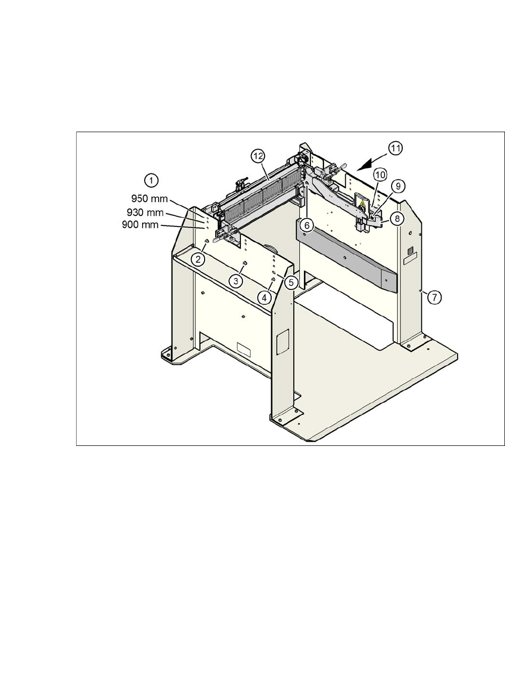
7.5.5 Adjusting the Docking Station to the PCB Conveyor Height
The COT insert for the docking station can be easily converted to PCB conveyor heights of 900,
930 or 950 mm.
7
Fig. 7.5 - 4 Adjusting the docking station to the PCB conveyor height
(1) Holes for the PCB conveyor height
(2) Hexagonal nut M8 and washer, 2x each
(3) Hexagonal nut M8 and washer, 2x each
(4) Hexagonal nut M8 and washer, 2x each
(5) Slot for height adjustment
(6) Hexagon socket-head screw M8x40, 6x
(7) Hexagon socket-head screw M5x12, 4
(8) Guidance
(9) Hexagon socket-head screw M8x18, 2x
(10) Side panel, COT insert
(11) Docking station outer cover
(12) Feeder module control unit (FCU)
User Manual SIPLACE CA-Series 7 Component and Die Handling
From software version SC.708.0 Edition 12/2014 EN -DRAFT 7.5 Docking Station for the SIPLACE X-Series Component Trolley
443
7.5.5.1 Tools
You will need the following tools to adjust the height of the COT insert:
– Allen wrench, set
– Fork wrench, SW 13
7.5.5.2 Converting the Component Trolley Docking Unit to Other Heights
7
Loosen the two hexagon socket-head screws M8x18 (item 6 in fig. 7.5 - 4, page 442) and re-
move the left and right guidance (item 5 in fig. 7.5 - 4
).
Loosen the 4 hexagon socket-head screws M5x12. Hold the cover panel tight so that it does
not fall down.
Remove the panel.
Loosen the 6 hexagon socket-head screws M8 (item 2 in fig. 7.5 - 4, page 442) and remove
the 6 washers.
Ask a second person to hold the COT insert, while you remove the 6 hexagon socket-head
screws M8x40 (item 3 in fig. 7.5 - 4
).
Position the COT insert (item 7 in fig. 7.5 - 4) at the required height (item 1).
7
Insert the 6 hexagon socket-head screws M8x40 (item 3 in fig. 7.5 - 4) into the holes in the
COT insert and docking station.
Fix the COT insert with the 6 M8 nuts and washers (item 2 in fig. 7.5 - 4, page 442).
Fasten the left and right guides (item 5 in fig. 7.5 - 4) with the hexagon socket-head screw
M8x18 (item 6 in fig. 7.5 - 4
).
If removed, refasten the covers (item 8 in fig. 7.5 - 4) with the 4 hexagon socket-head screws
M5x12.
WARNING
Heavy COT insert!
When converting the COT insert, enlist the help of a second person.
Disconnect the docking station from the power supply.
Disconnect the docking station from the compressed air supply
WARNING
Risk of damage!
Raising and lowering the COT insert could lead to cable damage.
Make sure that you do not damage the cables when raising or lowering.