00197498-03_UM_SiplaceCA-Serie_EN.pdf - 第444页
7 Component and Die Handling User Manual SIPLACE CA-Series 7.5 Docking Station for the SIPLACE X-Series Component Tr olley From software version SC.708.0 Edition 12/2014 EN -DRAFT 444 7.5.6 Controls and Displays 7 Fig. 7…
User Manual SIPLACE CA-Series 7 Component and Die Handling
From software version SC.708.0 Edition 12/2014 EN -DRAFT 7.5 Docking Station for the SIPLACE X-Series Component Trolley
443
7.5.5.1 Tools
You will need the following tools to adjust the height of the COT insert:
– Allen wrench, set
– Fork wrench, SW 13
7.5.5.2 Converting the Component Trolley Docking Unit to Other Heights
7
Loosen the two hexagon socket-head screws M8x18 (item 6 in fig. 7.5 - 4, page 442) and re-
move the left and right guidance (item 5 in fig. 7.5 - 4
).
Loosen the 4 hexagon socket-head screws M5x12. Hold the cover panel tight so that it does
not fall down.
Remove the panel.
Loosen the 6 hexagon socket-head screws M8 (item 2 in fig. 7.5 - 4, page 442) and remove
the 6 washers.
Ask a second person to hold the COT insert, while you remove the 6 hexagon socket-head
screws M8x40 (item 3 in fig. 7.5 - 4
).
Position the COT insert (item 7 in fig. 7.5 - 4) at the required height (item 1).
7
Insert the 6 hexagon socket-head screws M8x40 (item 3 in fig. 7.5 - 4) into the holes in the
COT insert and docking station.
Fix the COT insert with the 6 M8 nuts and washers (item 2 in fig. 7.5 - 4, page 442).
Fasten the left and right guides (item 5 in fig. 7.5 - 4) with the hexagon socket-head screw
M8x18 (item 6 in fig. 7.5 - 4
).
If removed, refasten the covers (item 8 in fig. 7.5 - 4) with the 4 hexagon socket-head screws
M5x12.
WARNING
Heavy COT insert!
When converting the COT insert, enlist the help of a second person.
Disconnect the docking station from the power supply.
Disconnect the docking station from the compressed air supply
WARNING
Risk of damage!
Raising and lowering the COT insert could lead to cable damage.
Make sure that you do not damage the cables when raising or lowering.
7 Component and Die Handling User Manual SIPLACE CA-Series
7.5 Docking Station for the SIPLACE X-Series Component Trolley From software version SC.708.0 Edition 12/2014 EN -DRAFT
444
7.5.6 Controls and Displays
7
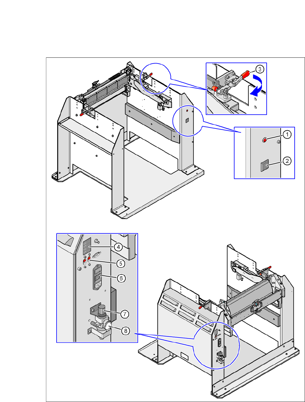
Fig. 7.5 - 5 Docking station - controls and displays
User Manual SIPLACE CA-Series 7 Component and Die Handling
From software version SC.708.0 Edition 12/2014 EN -DRAFT 7.5 Docking Station for the SIPLACE X-Series Component Trolley
445
Legend for fig. 7.5 - 5
(1) Control lamp for mains power supply
(2) Button for locking and unlocking all feeder modules on the component trolley
(3) Clamping lever for fastening the changeover table - lever in position "closed"
(4) Label with diagram of switch S1 and S2 for addressing the CAN bus
(5) Switch S1 and S2 for setting the CAN bus address
(6) Mains switch
(7) Rotary knob for setting the operating pressure
(8) Manometer for showing the operating pressure
7.5.7 Docking the SIPLACE X-Series Component Trolley onto the Docking Station
7
Open the two horizontal tensioner, by moving them in the direction of the arrow (item 3 in fig.
7.5 - 5
, page 444).
Push the component trolley carefully into the docking station. This will raise the component
table.
Make sure that the component trolley is standing fully on the base plate of the docking station.
Close the two horizontal tensioner (item 3 in fig. 7.5 - 5, page 444.
The changeover table will be lifted to its final position and locked into place.
Use the button (item 2 in fig. 7.5 - 5) to lock/unlock all feeder modules on the changeover ta-
ble.
7.5.8 Undocking the SIPLACE X-Series Component Trolley from the Docking Sta-
tion
7
Open the two horizontal tensioner (item 3 in fig. 7.5 - 5, page 444).
The component table is lowered.
Now pull the component trolley out of the docking station.
WARNING
Only component trolleys from the SIPLACE X-Series may be operated at this docking sta-
tion.
While docking, do not reach into the areas between component trolley and docking
station.
WARNING
While docking, do not reach into the areas between component trolley and docking
station.