00197498-03_UM_SiplaceCA-Serie_EN.pdf - 第450页
8 Station Extensions User manua l SIPLACE CA-Series 8.1 Nozzle Changers From software version SC.708.0 Edition 12/2014 EN -DRAFT 450 8 Fig. 8.1 - 4 Position of nozzle changers fo r t he SIPLACE SpeedSt ar (C&P20) - e…
User manual SIPLACE CA-Series 8 Station Extensions
From software version SC.708.0 Edition 12/2014 EN -DRAFT 8.1 Nozzle Changers
449
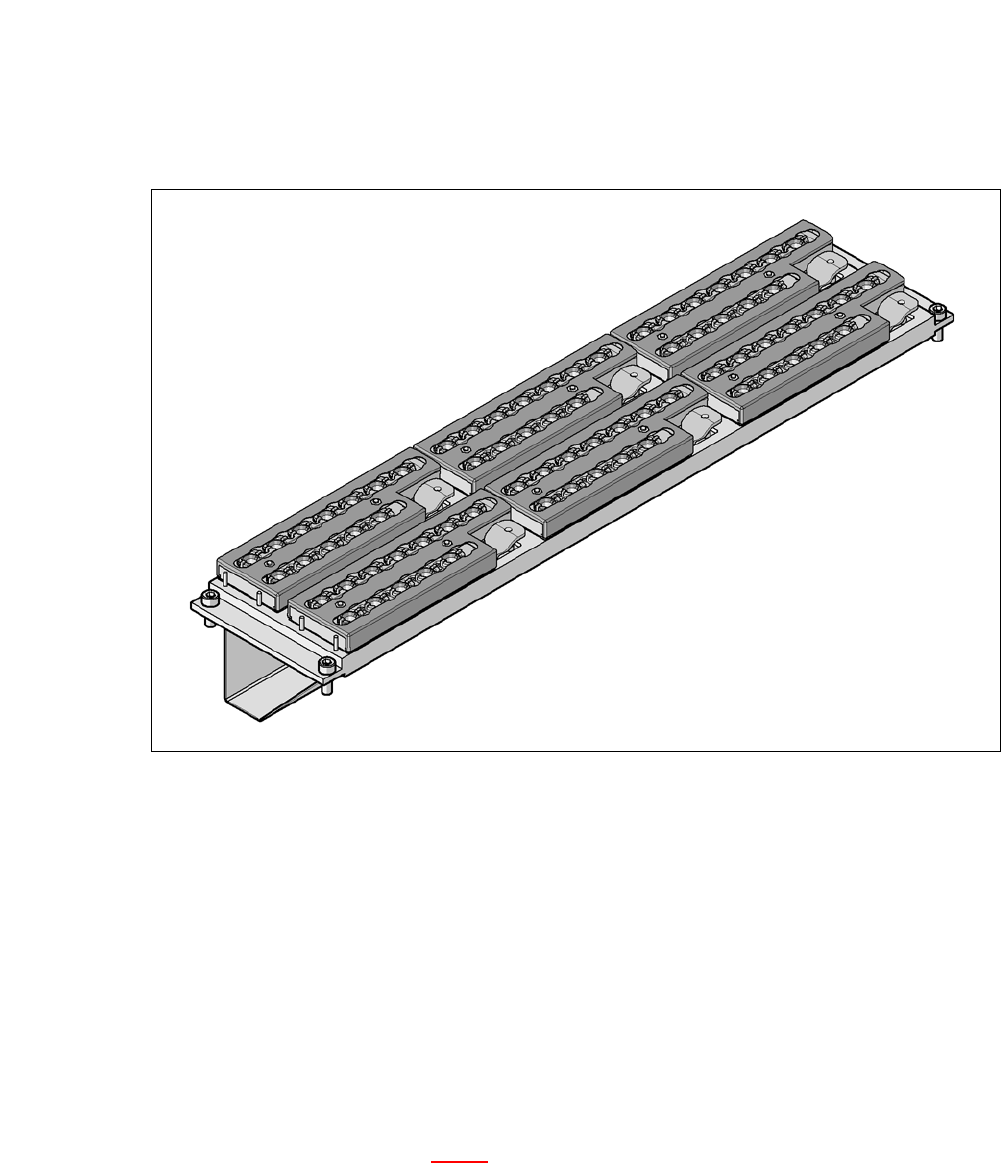
8.1.2 Nozzle Changers for the SIPLACE SpeedStar (C&P20 M)
8
Fig. 8.1 - 3 Nozzle changers for the SIPLACE SpeedStar (C&P20 M)
This nozzle changer can hold up to 6 magazines, each with 12 nozzle holders. The magazines
are seated on a common support. They are centered with two parallel pins and fixed in place with
4 snap fasteners.
The correct seat of the magazines on the basic nozzle changer body is monitored by micros-
witches, to prevent a collision of the placement head with any magazines projecting upwards. All
magazine locations must be filled since the safety circuit stops the machine in response to missing
magazines or magazines that are not seated correctly.
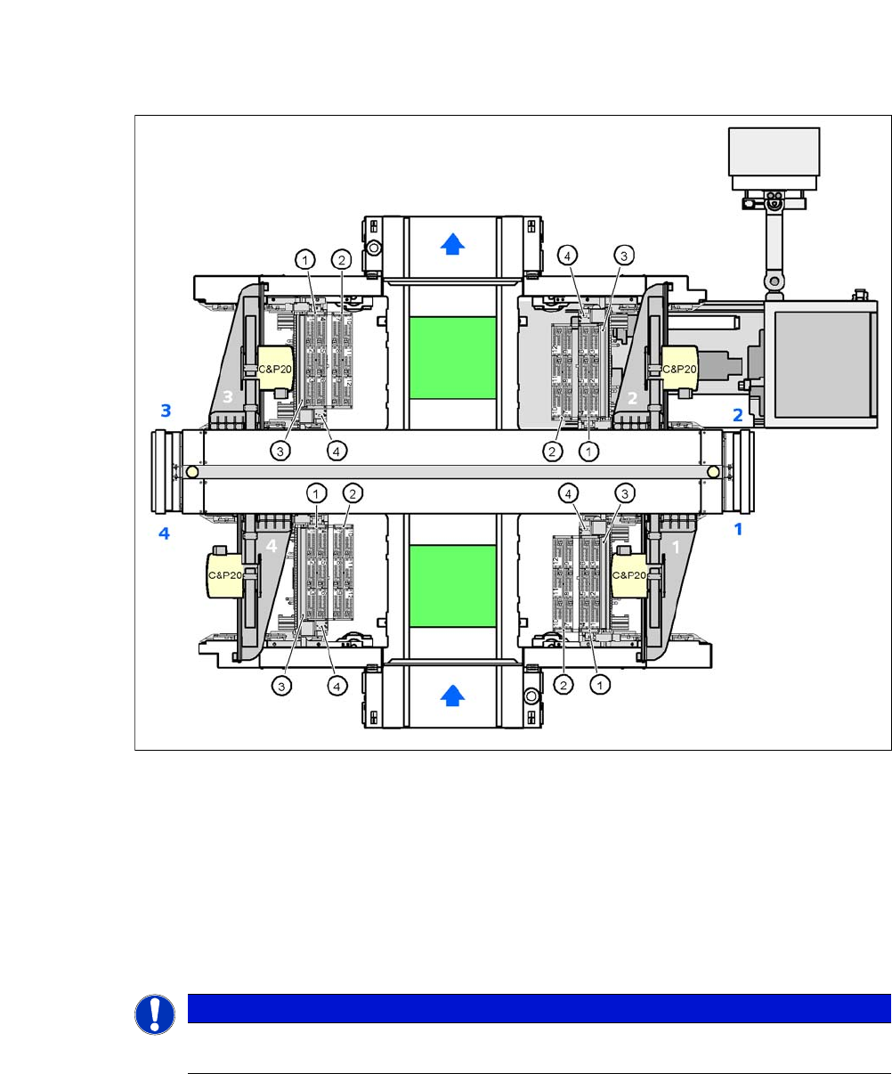
8.1.2.1 Position of the Nozzle Changers for the C&P20 Head on the CA4 Machine
The locations 1, 2, 3 and 4 can accommodate up to 2 nozzle changers for the SIPLACE SpeedStar
(C&P20 M) (item 1 and 2 in fig. 8.1 - 4
). This gives a total capacity of 8 nozzle changers with 48
magazines and a total of 576 nozzle holders.
8 Station Extensions User manual SIPLACE CA-Series
8.1 Nozzle Changers From software version SC.708.0 Edition 12/2014 EN -DRAFT
450
8
Fig. 8.1 - 4 Position of nozzle changers for the SIPLACE SpeedStar (C&P20) - example
8
8
(1) Nozzle changer, "row 1"
(2) Nozzle changer, "row 2"
(3) Reject bin for components
(4) Take-off device and reject bin for nozzles
(5) Nozzle magazine
PLEASE NOTE
When an SWS with a C&P20 nozzle changer is used, one row is installed by default. A
second row is available on request.
User manual SIPLACE CA-Series 8 Station Extensions
From software version SC.708.0 Edition 12/2014 EN -DRAFT 8.1 Nozzle Changers
451
8.1.2.2 Technical Data
8
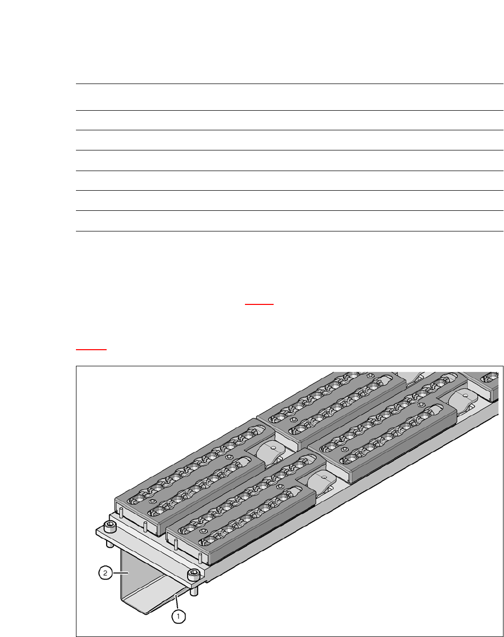
8.1.2.3 Assembly
The nozzle changers "row 1" (see fig. 8.1 - 4) are fitted as a standard at locations without SWS
and are fixed in each case to the COT insert. They are equipped with a take-off device and reject
bin. The "row 2" nozzle changer is available for order as an optional add-on kit (see section
8.1.2.8
).
8
Fig. 8.1 - 5 Assembly position
(1) Sloping side points towards the COT insert
(2) Vertical side points towards the PCB conveyor
Nozzle changers for the SIPLACE SpeedStar (C&P20 M)
Dimensions (length x width x height) 449 x 94.5 x 79 mm³
Number of magazines 6 with 12 nozzle garages each
*a
*)a All 6 magazines have to be set up
Number of nozzle holders 72
Nozzle types 10xx, 11xx and 12xx
Nozzle changeover time Approx. 2s per nozzle
Compressed air connection 0.48 MPa (4.8 bar)