00197498-03_UM_SiplaceCA-Serie_EN.pdf - 第452页
8 Station Extensions User manua l SIPLACE CA-Series 8.1 Nozzle Changers From software version SC.708.0 Edition 12/2014 EN -DRAFT 452 Align the nozzle chang er so that the sloping side po ints towards the COT insert. 8 …
User manual SIPLACE CA-Series 8 Station Extensions
From software version SC.708.0 Edition 12/2014 EN -DRAFT 8.1 Nozzle Changers
451
8.1.2.2 Technical Data
8
8.1.2.3 Assembly
The nozzle changers "row 1" (see fig. 8.1 - 4) are fitted as a standard at locations without SWS
and are fixed in each case to the COT insert. They are equipped with a take-off device and reject
bin. The "row 2" nozzle changer is available for order as an optional add-on kit (see section
8.1.2.8
).
8
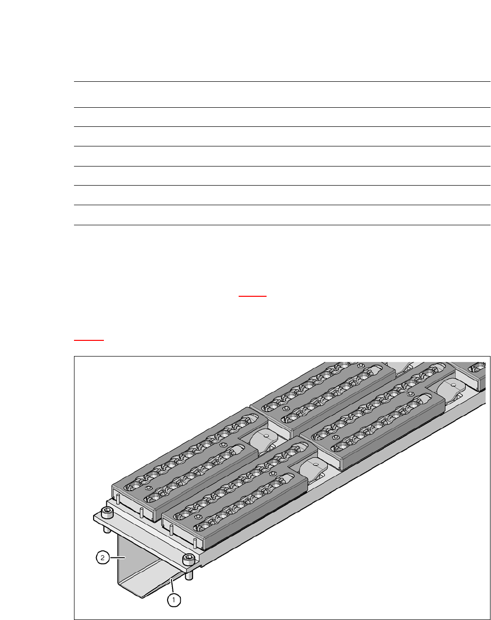
Fig. 8.1 - 5 Assembly position
(1) Sloping side points towards the COT insert
(2) Vertical side points towards the PCB conveyor
Nozzle changers for the SIPLACE SpeedStar (C&P20 M)
Dimensions (length x width x height) 449 x 94.5 x 79 mm³
Number of magazines 6 with 12 nozzle garages each
*a
*)a All 6 magazines have to be set up
Number of nozzle holders 72
Nozzle types 10xx, 11xx and 12xx
Nozzle changeover time Approx. 2s per nozzle
Compressed air connection 0.48 MPa (4.8 bar)
8 Station Extensions User manual SIPLACE CA-Series
8.1 Nozzle Changers From software version SC.708.0 Edition 12/2014 EN -DRAFT
452
Align the nozzle changer so that the sloping side points towards the COT insert.
8
8
8.1.2.4 Functions
The nozzles are located in nozzle garages and are fixed by a movable locking plate. A pneumatic
cylinder moves the locking plate by 7 mm. Depending on the position of the locking plate, all noz-
zles are either clamped into place or released. The default position of the locking plate, i.e. if there
is no nozzle change in progress, is "closed".
Each magazine on the nozzle changer has two positioning fiducials for detecting the position and
orientation of the magazine. The magazine locations are numbered from 1-6 for the nozzle chang-
ers of "row 1" and from 7-12 for the "row 2" nozzle changers (see fig. 8.1 - 4
). The 12 nozzle ga-
rages in the magazines are also numbered consecutively (see fig. 8.1 - 8
).
8
Picking Up Nozzles 8
– The Z axis of the Collect&Place head moves down.
– The locking plate (item 2 in fig. 8.1 - 6
) opens, providing access to the nozzles.
– The nozzle is taken up by the sleeve of the Collect&Place head.
– The Z axis moves up.
WARNING
Risk of head crashes with mixed configurations!
There is a risk of head crashes with mixed configurations.
Only install the corresponding nozzle changer for each placement head, with the noz-
zle magazines for the respective placement head.
WARNING
Risk of collisions!
If the wrong reject bins are used, there is a risk of collision with the component sensor of
the C&P20 placement head (see section 2.6.9
, page 77).
Only use reject bins marked [03003719-06] at locations without SWS.
Only use reject bins marked [03070917-01] at locations without SWS.
PLEASE NOTE
Special magazines
Special magazines can be produced on request by ASM Assembly Systems GmbH &
Co.KG and will be marked accordingly.

User manual SIPLACE CA-Series 8 Station Extensions
From software version SC.708.0 Edition 12/2014 EN -DRAFT 8.1 Nozzle Changers
453
Placing a Nozzle Down 8
– The locking plate (item 2 in fig. 8.1 - 6) opens, providing access to the nozzles.
– The Z axis of the Collect&Place head moves down and places the nozzle down.
– The locking plate closes.
– The Z axis of the Collect&Place head moves up again.
Rejecting Defective Nozzles 8
– When it is at the reject unit (item 4 in fig. 8.1 - 4), the Z axis moves the Collect&Place head
down and the defective nozzle to the opening of the reject device. The nozzle is turned and
does not fit through the opening any longer.
– The Z axis moves up again and the nozzle is stripped from the sleeve opening.
– The nozzle drops into the reject bin.