00197498-03_UM_SiplaceCA-Serie_EN.pdf - 第463页
User manual SIPLACE CA-Series 8 Station Extensions From software version SC.708.0 Edition 12/20 14 EN -DRAFT 8.1 Nozzle Changers 463 8.1.3.4 Assembly The nozzle changers are fixed to the COT insert. 8 Fig. 8.1 - 13 Assem…

8 Station Extensions User manual SIPLACE CA-Series
8.1 Nozzle Changers From software version SC.708.0 Edition 12/2014 EN -DRAFT
462
8.1.3.2 Technical Data
8
8.1.3.3 Nozzle Changer "Row 2" for the SIPLACE MultiStar
The "nozzle changer for row 2" option enables you to configure an additional row of nozzle chang-
ers for the SIPLACE MultiStar.
The retrofit package contains the nozzle changer and an assembly kit.
Nozzle changer for the SIPLACE MultiStar and SIPLACE SpeedStar
Dimensions (length x width x height) 449 x 94.5 x 55 mm³
Number of nozzle holders
Type 20xx 60
Type 28xx 9
Type 10xx, 11xx, 12xx 72
Nozzle types 20xx (CPP head)
28xx (CPP head)
10xx, 11xx, 12xx (C&P20 head)
Nozzle changeover time Approx. 2s per nozzle
Compressed air connection 0.48 MPa (4.8 bar)
User manual SIPLACE CA-Series 8 Station Extensions
From software version SC.708.0 Edition 12/2014 EN -DRAFT 8.1 Nozzle Changers
463
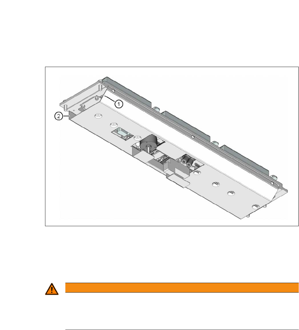
8.1.3.4 Assembly
The nozzle changers are fixed to the COT insert.
8
Fig. 8.1 - 13 Assembly position of nozzle changer - view from below
(1) Sloping side points towards the COT insert
(2) Vertical side points towards the PCB conveyor
Align the nozzle changer so that the sloping side points towards the COT insert.
8
WARNING
Risk of head crashes with mixed configurations!
There is a risk of head crashes with mixed configurations.
Only install the associated nozzle changer for each placement head, with the nozzle
magazines for the respective placement head.
8 Station Extensions User manual SIPLACE CA-Series
8.1 Nozzle Changers From software version SC.708.0 Edition 12/2014 EN -DRAFT
464
8.1.3.5 Notes on Operation
When you fill a magazine with a certain nozzle type for the first time, attach an adhesive label
to identify the type.
8
Open the locking plate and place the nozzles in the nozzle holders.
Close the locking plate so that the nozzles cannot drop out of the magazines.
8
8
Programming the nozzle changer is described in the SIPLACE Pro user manual.
8.1.3.6 Changing the Magazine
Press the lever (item 1 in fig. 8.1 - 14, page 465), to release the magazine from the balls of the
snap fasteners (item 5 in fig. 8.1 - 14
, page 465). Lift the magazine off the base.
8
PLEASE NOTE
Fill the magazines off the machine and always replace complete magazines.
CAUTION
Filling up magazines!
Before you fill magazines, make sure that all the nozzles on the Collect&Place head
have
been returned to their magazines.
PLEASE NOTE
Risk of jamming!
If components fall onto magazines, there is a risk that the locking plate could jam.
Do not allow components to drop onto the magazines.
You should therefore regularly clean the magazines and free locations.
WARNING
Risk of head crashes with protruding lever
Any lever that is protruding over the magazine (item 1 in fig 8.1 - 14
) can result in a head
crash.
You should therefore make sure that the lever does not protrude over the maga-
zines.