00197498-03_UM_SiplaceCA-Serie_EN.pdf - 第476页
8 Station Extensions User manua l SIPLACE CA-Series 8.4 Component Camera for the MultiStar From software version SC.708.0 Edition 12/2014 EN -DRAFT 476 8.4 Component Camera for the MultiS t ar 8.4.1 Component Camera, St …
User manual SIPLACE CA-Series 8 Station Extensions
From software version SC.708.0 Edition 12/2014 EN -DRAFT 8.3 Component Camera for the TwinStar, FC Camera
475
8.3.2 Safety Instructions
8
8.3.3 Technical Data
8
8
8
WARNING
Placement head change
When changing the placement head from the TwinStar to the SpeedStar, dismantle
the stationary component cameras type 33, 55 x 45, digital and 25, 16 x 16 digital (FC
camera) of the TwinStar, to prevent the SpeedStar from colliding with the camera
housings.
When changing the placement head from TwinStar to MultiStar, the stationary com-
ponent camera, type 33, 55 x 45, digital, is fitted in the bottom position.
Component dimensions 0.2 x 0.2 mm² to 16 x 16 mm² for simple measurement of component
Component range 0402 to SO, PLCC, QFP, sockets, plugs, BGA, special components,
bare dies, flip-chips, shields
Min. lead pitch 0.25 mm
Min. lead width 0.1 mm
Min. ball pitch 0.14 mm
Min. ball diameter 0.08 mm
Field of vision 19.4 x 19.4 mm²
Illumination mode Front-illumination (6 levels, programmable as required)
8 Station Extensions User manual SIPLACE CA-Series
8.4 Component Camera for the MultiStar From software version SC.708.0 Edition 12/2014 EN -DRAFT
476
8.4 Component Camera for the MultiStar
8.4.1 Component Camera, Stationary P&P, Type 33, 55 x 45, Digital
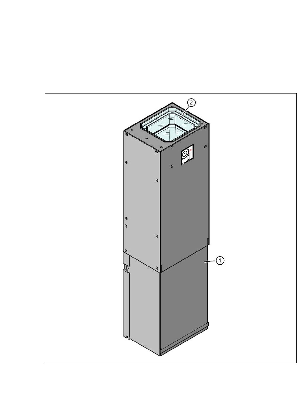
Item no. 00119782-xx Stationary camera for the CPP head
8
Fig. 8.4 - 1 Structure for the stationary P&P component camera, type 33, 55 x 45, digital
(1) Camera housing with integral camera and camera amplifier
(2) Glass plate - illumination and lens levels below

User manual SIPLACE CA-Series 8 Station Extensions
From software version SC.708.0 Edition 12/2014 EN -DRAFT 8.4 Component Camera for the MultiStar
477
8.4.1.1 Component Range
For an overview of the components which are centered with the stationary camera, refer to section
3.5.2.3
, page 133.
8.4.1.2 Technical Data
8
8
Component dimensions 0.5 x 0.5 mm² to 55 x 45 mm²
Component range 0402, MELF, SO, PLCC, QFP, electrolytic capacitors, BGA
Min. lead pitch 0.3 mm
Min. lead width 0.15 mm
Min. ball pitch 0.35 mm
Min. ball diameter 0.2 mm
Field of vision 65 x 50 mm²
Illumination mode Front-illumination (6 levels, programmable as required)