00197498-03_UM_SiplaceCA-Serie_EN.pdf - 第478页
8 Station Extensions User manua l SIPLACE CA-Series 8.5 PCB Camera Multicolor, Type 24, Digital Fro m software version SC.708.0 Edition 12/2014 EN -DRAFT 478 8.5 PCB Camera Multicolor , T ype 24, Digit al 8.5.1 S tructur…

User manual SIPLACE CA-Series 8 Station Extensions
From software version SC.708.0 Edition 12/2014 EN -DRAFT 8.4 Component Camera for the MultiStar
477
8.4.1.1 Component Range
For an overview of the components which are centered with the stationary camera, refer to section
3.5.2.3
, page 133.
8.4.1.2 Technical Data
8
8
Component dimensions 0.5 x 0.5 mm² to 55 x 45 mm²
Component range 0402, MELF, SO, PLCC, QFP, electrolytic capacitors, BGA
Min. lead pitch 0.3 mm
Min. lead width 0.15 mm
Min. ball pitch 0.35 mm
Min. ball diameter 0.2 mm
Field of vision 65 x 50 mm²
Illumination mode Front-illumination (6 levels, programmable as required)
8 Station Extensions User manual SIPLACE CA-Series
8.5 PCB Camera Multicolor, Type 24, Digital From software version SC.708.0 Edition 12/2014 EN -DRAFT
478
8.5 PCB Camera Multicolor, Type 24, Digital
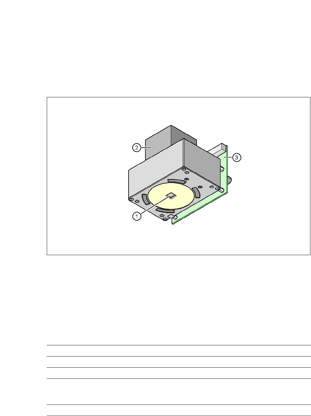
8.5.1 Structure
[00119774-xx] PCB camera, X-Series, multicolor, type 24
8
Fig. 8.5 - 1 PCB camera multicolor, type 24, digital
(1) PCB camera lens and illumination
(2) Camera amplifier
(3) Illumination control
8
8.5.2 Technical Data
8
Field of vision 5.7 mm x 5.7 mm
Distance from the focus plane 28 mm
Illumination mode Front-illumination (5 levels, programmable as required)
Fiducial size 0.3 mm to 2.5 mm edge length for a PCB feeder tolerance
of ± 1.0 mm
to 3.0 mm edge length for a PCB feeder tolerance of < 1.0 mm
Bad fiducial size 0.3 mm to 3.0 mm edge length

User manual SIPLACE CA-Series 8 Station Extensions
From software version SC.708.0 Edition 12/2014 EN -DRAFT 8.5 PCB Camera Multicolor, Type 24, Digital
479
8.5.3 Illumination Types
The following types of illumination can be selected on the multicolor PCB camera:
– White illumination
This illumination mode is used for standard boards with tin-plated fiducials.
– Blue oblique illumination
Used with bare fiducials on light-colored base materials, such as ceramic or CEM, this can
generally make a significant improvement to the contrast. Fiducials covered with solder resist
can also be detected better on a light background.
– Infrared illumination
This illumination mode is particularly advisable for fiducials which are covered with solder
stop varnish or for fiducials made of flex material. When using silver or platinum fiducials on
a ceramic base, this type of illumination could also achieve better recognition results. This
should be checked in advance by performing a test centering/placement run.
8.5.4 Fiducial and Ink Spot Criteria
Fiducial and ink spot criteria are described in the sections 3.12.4.3 and 3.12.4.4, page 185.