00197498-03_UM_SiplaceCA-Serie_EN.pdf - 第479页
User manual SIPLACE CA-Series 8 Station Extensions From software version SC.708.0 Edition 12/20 14 EN -DRAFT 8.5 PCB Camera Multicolor, Type 24, Digital 479 8.5.3 Illumination T ypes The following types of illumination c…
8 Station Extensions User manual SIPLACE CA-Series
8.5 PCB Camera Multicolor, Type 24, Digital From software version SC.708.0 Edition 12/2014 EN -DRAFT
478
8.5 PCB Camera Multicolor, Type 24, Digital
8.5.1 Structure
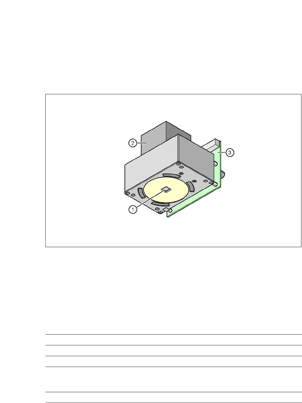
[00119774-xx] PCB camera, X-Series, multicolor, type 24
8
Fig. 8.5 - 1 PCB camera multicolor, type 24, digital
(1) PCB camera lens and illumination
(2) Camera amplifier
(3) Illumination control
8
8.5.2 Technical Data
8
Field of vision 5.7 mm x 5.7 mm
Distance from the focus plane 28 mm
Illumination mode Front-illumination (5 levels, programmable as required)
Fiducial size 0.3 mm to 2.5 mm edge length for a PCB feeder tolerance
of ± 1.0 mm
to 3.0 mm edge length for a PCB feeder tolerance of < 1.0 mm
Bad fiducial size 0.3 mm to 3.0 mm edge length

User manual SIPLACE CA-Series 8 Station Extensions
From software version SC.708.0 Edition 12/2014 EN -DRAFT 8.5 PCB Camera Multicolor, Type 24, Digital
479
8.5.3 Illumination Types
The following types of illumination can be selected on the multicolor PCB camera:
– White illumination
This illumination mode is used for standard boards with tin-plated fiducials.
– Blue oblique illumination
Used with bare fiducials on light-colored base materials, such as ceramic or CEM, this can
generally make a significant improvement to the contrast. Fiducials covered with solder resist
can also be detected better on a light background.
– Infrared illumination
This illumination mode is particularly advisable for fiducials which are covered with solder
stop varnish or for fiducials made of flex material. When using silver or platinum fiducials on
a ceramic base, this type of illumination could also achieve better recognition results. This
should be checked in advance by performing a test centering/placement run.
8.5.4 Fiducial and Ink Spot Criteria
Fiducial and ink spot criteria are described in the sections 3.12.4.3 and 3.12.4.4, page 185.
8 Station Extensions User manual SIPLACE CA-Series
8.6 Matrix Tray Changer From software version SC.708.0 Edition 12/2014 EN -DRAFT
480
8.6 Matrix Tray Changer
Item no. 00116438-xx SIPLACE Matrix Tray Changer (MTC)
8.6.1 Safety Instructions
8
8
8.6.2 Description
The Matrix Tray Changer supports the storing and fully automatic changeover of up to 100 waffle
pack trays. The levels (storage positions in the towers) for the waffle pack trays are numbered up-
wards, from bottom to top.
The towers move independently of one another, in a vertical direction, until the selected magazine
reaches the access area of the feed axis. The horizontal feed axis transports the waffle pack tray
from the tower to the access area of the placement head.
Tower 1 has 30 levels, on each of which 2 JEDEC trays or one large tray up to a size of 240 x 340
mm² can be accommodated by the waffle pack tray carriers.
Tower 2 has a capacity of 40 levels for JEDEC trays.
The matrix tray changer has an integral chassis, and is easy to move to other locations. It is sup-
plied with the PCB conveyor height set for the customer-specific machine but can be quickly and
easily adapted to conveyor heights of 900, 930, and 950 mm.
WARNING
Risk of injuries!
Risk of injuries if you reach into the gap between the Matrix Tray Changer and the ma-
chine base while the machine is running.
Do not reach into the gaps between the matrix tray changer and the machine base
while the machine is running.
WARNING
Requirement for operation: Matrix Tray Changer docked onto machine
Do not use the Matrix Tray Changer, if it is not docked onto the machine.
Only connect the power supply cable to the external power supply or only disconnect
it if the Matrix Tray Changer is docked onto the machine.