00197498-03_UM_SiplaceCA-Serie_EN.pdf - 第496页
8 Station Extensions User manua l SIPLACE CA-Series 8.12 Vision Teach Place From software version SC.708.0 Edition 12/2014 EN -DRAFT 496 8.12.1 Overview The vision teach station is a system for c reating and testing pack…
User manual SIPLACE CA-Series 8 Station Extensions
From software version SC.708.0 Edition 12/2014 EN -DRAFT 8.12 Vision Teach Place
495
8.12 Vision Teach Place
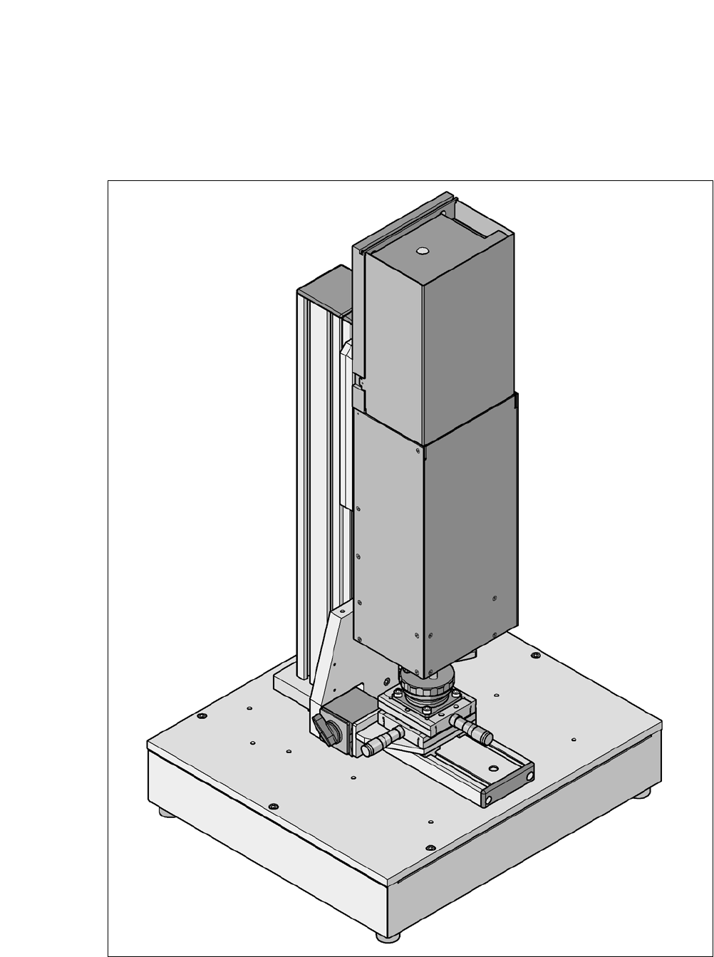
[00119788-xx] Vision teach station
8
Fig. 8.12 - 1 Vision teach station with component camera, type 33

8 Station Extensions User manual SIPLACE CA-Series
8.12 Vision Teach Place From software version SC.708.0 Edition 12/2014 EN -DRAFT
496
8.12.1 Overview
The vision teach station is a system for creating and testing package form descriptions for com-
ponents to be processed on SIPLACE placement machines.
The vision teach station essentially consists of the following components:
– Base module with electronic circuits and one or two component cameras
– Mini-tower PC
WINDOWS XP operating system 8
SIPLACE Vision image processing software 8
SIPLACE Pro database server 8
Camera interfaces: CAN bus card and camera bus card 8
8.12.2 Description
The vision teach station is used to create and test descriptions for package forms for any place-
ment machine and to run component inspections.
The component shape descriptions specified can be saved in the SIPLACE Pro database at the
Vision teach station and then transferred to the SIPLACE Pro database of the production system.
You can also download vision screenshots from placement machines to the vision teach station
for analysis. Only multiple component measurements still have to be carried out on the placement
machine.
8.12.3 Benefits
The major advantage of this offline system is that it is totally independent of the production system,
and no production system resources have to be used for creating and testing package form de-
scriptions. As a result, there is no loss of productivity due to the description and testing of package
forms. The time taken to introduce new products can also be considerably reduced with this inde-
pendent system.

User manual SIPLACE CA-Series 8 Station Extensions
From software version SC.708.0 Edition 12/2014 EN -DRAFT 8.12 Vision Teach Place
497
8.12.4 Component Cameras Supported
The Vision teach place supports the following component cameras:
Component camera Component range Use on placement machine
C&P, type 23, 6x6 ,
digital
01005 to 6 mm x 6 mm Head camera for the C&P20 head
C&P, type 41, 6x6 ,
digital
03015 to 6 mm x 6 mm Head camera for the C&P20 head
C&P, type 29, 27 x 27,
digital
0201 to 27 mm x 27 mm
PLCC, SO, QFP, TSOP,
SOT, MELF, CHIP, IC, BGA
Head camera for the C&P6/C&P12
head
P&P, stationary, type 33,
55 x 45, digital
0402 to 55 mm x 45 mm,
MELF, SO, PLCC, QFP,
electrolytic capacitors, BGA,
connectors
Stationary camera for ICs and
connectors
P&P, stationary, type 25,
16 x 16, digital
0201 to 16 mm x 16 mm,
SO, PLCC, QFP, Socket,
connectors, BGA, special
components, Bare Die, Flip-
Chip, Shield
Stationary camera for flip-chip com-
ponents
P&P, stationary, type 36,
32 x 32, digital
0603 to 32 mm x 32 mm,
MELF, SO, PLCC, QFP,
electrolytic capacitors, BGA,
connectors
Stationary camera for ICs and con-
nectors on the D1 machine