00197498-03_UM_SiplaceCA-Serie_EN.pdf - 第67页
User Manual SIPLACE CA-Series 2 Operational Safety From software version SC.708.0 Edition 12/2014 EN -DRAFT 2.4 Laser Classification 67 2.4 Laser Classification 2.4.1 Laser Class 1 2.4.1.1 Classification of the Whole Mac…
2 Operational Safety User Manual SIPLACE CA-Series
2.3 Warning Labels on the SWS From software version SC.708.0 Edition 12/2014 EN -DRAFT
66
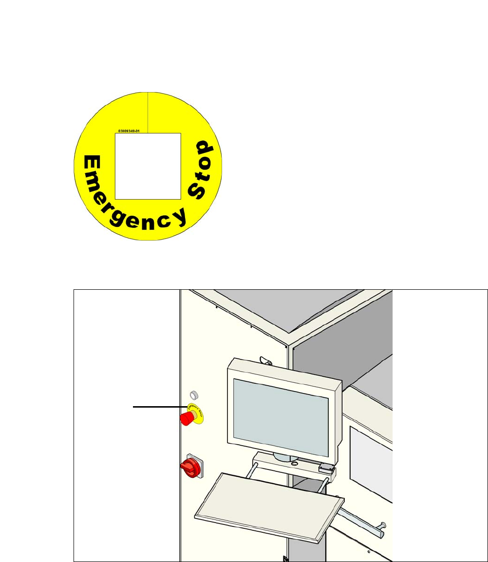
2.3.6 Warning Label W209 on the EMERGENCY STOP button
2
Fig. 2.3 - 10 W209 [03009349-01] (quantity per SWS: 1)
2
2
Fig. 2.3 - 11 Warning label W209 on the EMERGENCY STOP button
2
2
2
2
2
2
2
2
2
2
2
2
2
2
2
2
2
2
2
For Australia, Canada, Mexico and USA, warn-
ing label W209 is affixed to the extension kit in-
stead of the yellow ring on the EMERGENCY
STOP buttons.
W209
User Manual SIPLACE CA-Series 2 Operational Safety
From software version SC.708.0 Edition 12/2014 EN -DRAFT 2.4 Laser Classification
67
2.4 Laser Classification
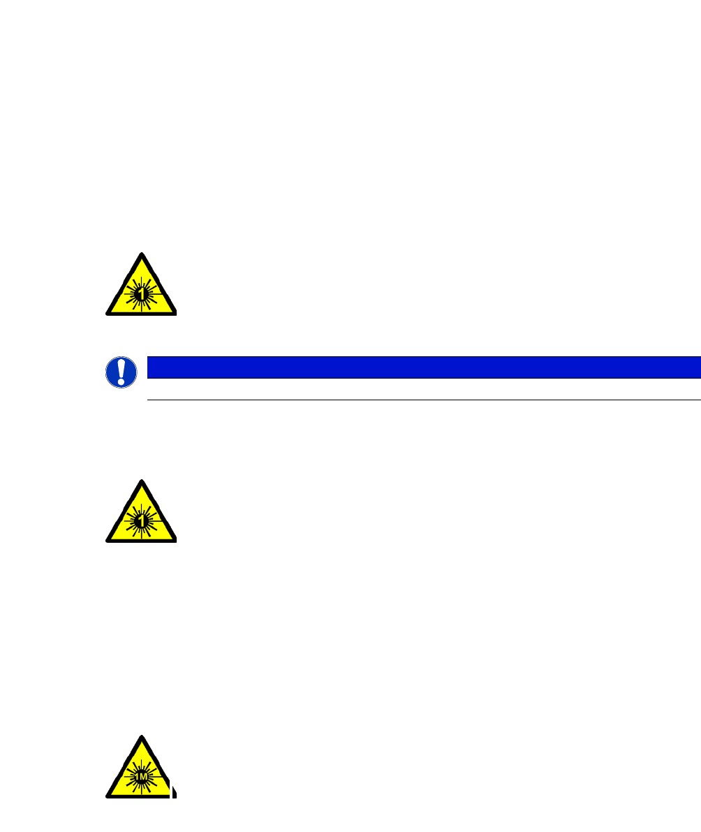
2.4.1 Laser Class 1
2.4.1.1 Classification of the Whole Machine
2
2
2.4.1.2 Classification of the Camera Systems
2
2.4.2 Laser Class 1M
Do not look directly at this with optical instruments!
2
PLEASE NOTE
Modules in laser classes 1 and 1M are not identified.
2
All installed camera systems and the whole machine when ready
for operation are assigned to laser class 1.
The laser classes are determined according to DIN EN 60825-
1:2001
2
The following camera systems are assigned to laser class 1:
– PCB camera multicolor, type 24, digital
– Component cameras
Stationary component camera P&P, type 33, 55 x 45, digital (
Stationary component camera P&P, type 25, 16 x 16, digital
2
The following camera systems are assigned to laser class 1M:
– Component camera C&P, type 41, 6 x 6 on the SIPLACE SpeedStar
(C&P20 M)
– Component camera C&P, type 30, 27 x 27 on MultiStar
2 Operational Safety User Manual SIPLACE CA-Series
2.5 Safety Instructions for Transportation From software version SC.708.0 Edition 12/2014 EN -DRAFT
68
2.4.3 Laser Class 2
The following modules are assigned to laser class 2:
– Laser light barrier, placement area 1 in the PCB conveyor
– Laser light barrier, placement area 2 in the PCB conveyor
– PCB barcode scanner
– Component sensor on the SIPLACE SpeedStar (C&P20 M)
– Component sensor on MultiStar (CPP)
2
2.5 Safety Instructions for Transportation
2.5.1 Transporting the Placement Machine
2
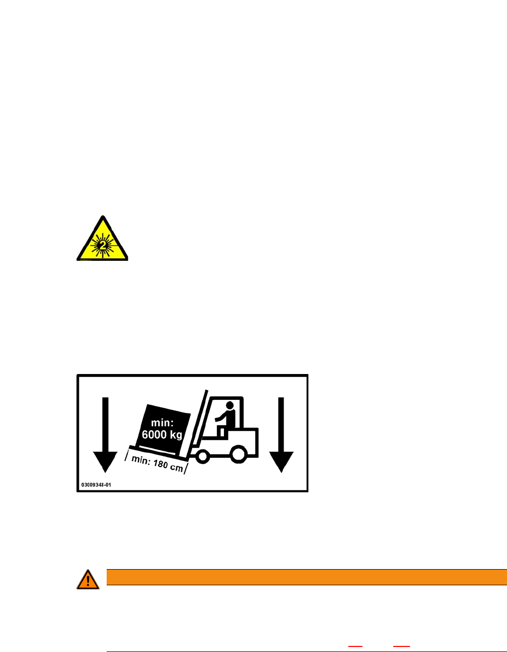
Use a fork-lift truck with the following specification to carry the machine:
Fork length:Min. 1800 mmCarrying power:Min. 6000 kgClear width between forks:Min. 350
mm 2
2
2
Laser radiation
Do not look into beam!
WARNING
Risk of tilting!
Risk of tilting, if the required specifications for the fork-lift truck are not observed.
Only use the specified fork-lift for transportation.
Transportation of the machine is described in section 5.2
, page 257.