00197498-03_UM_SiplaceCA-Serie_EN.pdf - 第83页
User Manual SIPLACE CA-Series 2 Operational Safety From software version SC.708.0 Edition 12/20 14 EN -DRAFT 2.8 Safety Features 83 Function 2 If one of the protective cove rs is swung upwards or if one of the cover flap…
2 Operational Safety User Manual SIPLACE CA-Series
2.8 Safety Features From software version SC.708.0 Edition 12/2014 EN -DRAFT
82
2.8 Safety Features
2.8.1 Protective Covers
2
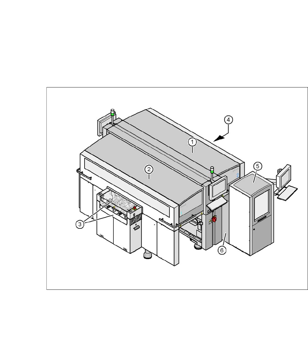
Fig. 2.8 - 1 Protective covers and other covers
(1) Protective cover
(2) Protective cover
(3) Cover flap and hand guard on the input conveyor
(4) Cover flap and hand guard on the output conveyor
(5) Magazine lift with sliding door
(6) Fixed cover on SWS
2
The traveling range of the gantries has two protective covers that can be swung upwards (items
1 and 2). There are side screens to prevent access to the inside of the machine from the side. The
two cover flaps (item 3 and 4) over the input or output belt of the PCB conveyor prevent access
to the PCB conveyor.
User Manual SIPLACE CA-Series 2 Operational Safety
From software version SC.708.0 Edition 12/2014 EN -DRAFT 2.8 Safety Features
83
Function 2
If one of the protective covers is swung upwards or if one of the cover flaps on the PCB conveyor
is lifted, the power supply to the gantry axes and SWS will be immediately interrupted. The gantry
axes and all SWS axes will come to a standstill. The message "Close cover" is displayed on the
screen.
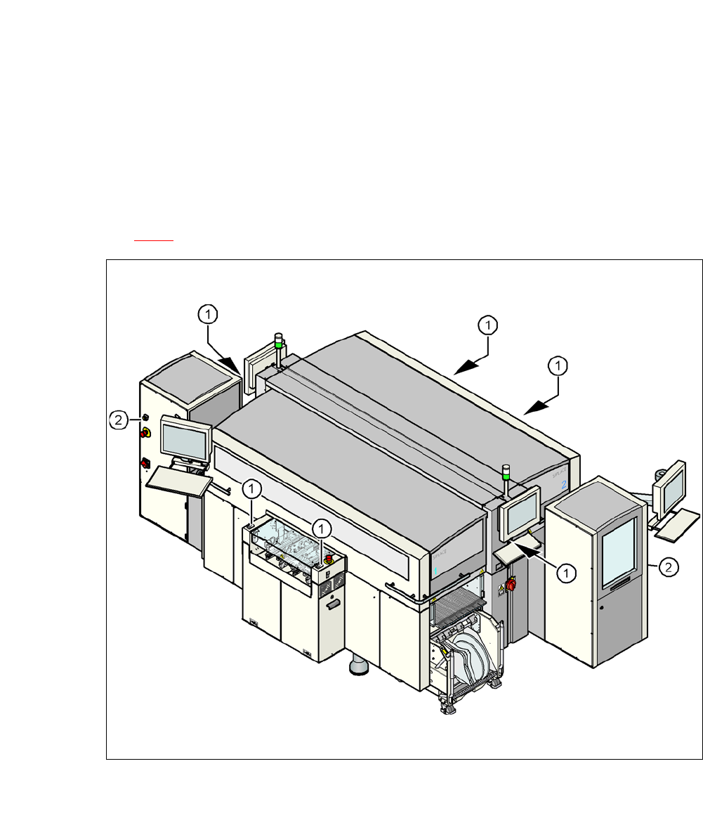
Close the protective covers and press one of the Start buttons on the machine (item 1 in fig.
2.8 - 2
).
2
Fig. 2.8 - 2 Position of the start and EMERGENCY STOP reset button (white) on the machine and on the SWS
(1) Start button (white) on the machine
(2) Operating status indicator (white) on the SWS
2 Operational Safety User Manual SIPLACE CA-Series
2.8 Safety Features From software version SC.708.0 Edition 12/2014 EN -DRAFT
84
2.8.2 Switches and Buttons on the Machine and on the SWS
2.8.2.1 Position of Switches and Buttons on the Machine and on the SWS
2
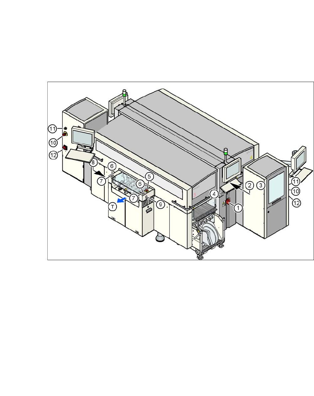
Fig. 2.8 - 3 Position of switches and buttons - view of the PCB output side
(1) Main switch on machine
(2) Stop button (black) on the operator panel on the power supply side
(3) Start button (white) on the operator panel on the power supply side
(4) Component counter on the operator panel on the power supply side
(5) EMERGENCY STOP button on the output side
(6) Start button (white) on the output side
(7) Stop button (black) on the output side
(8) Button (black) for docking the component trolley in or out, location 2
(9) Button (black) for docking the component trolley in or out, location 3
(10) EMERGENCY STOP button on the SWS
(11) Operating status indicator on the SWS
(12) Main Switch at the SWS
(T) PCB transport direction
2