00197498-03_UM_SiplaceCA-Serie_EN.pdf - 第89页
User Manual SIPLACE CA-Series 2 Operational Safety From software version SC.708.0 Edition 12/20 14 EN -DRAFT 2.8 Safety Features 89 Main power switch in OFF position 2 2 Main switch in ON position 2 After you switch on u…

2 Operational Safety User Manual SIPLACE CA-Series
2.8 Safety Features From software version SC.708.0 Edition 12/2014 EN -DRAFT
88
Protective cover switch 1, 2, 3 and 4 (items 1, 2, 3 and 4 in fig. 2.8 - 5) and protective cover for
the cover flaps on the input and output sides of the PCB conveyor (items 5 and 6 in fig.
2.8 - 5)2
These switches check whether the protective covers and the cover flaps are closed. When they
are closed, the EMERGENCY STOP contact and the signaling contact are closed. If one of the
covers or the cover flaps is opened, the EMERGENCY STOP contact and the signaling contact
open. Individual components are disabled or remain enabled (see fig. 2.8 - 8
, page 95).
2
2.8.2.3 Function of Switches and Buttons on the SWS
EMERGENCY STOP button, latching, with override protection according to EN 418 2
The EMERGENCY STOP button is red and latches in the ON position when pressed. When you
press the EMERGENCY STOP button, the switching contact of the EMERGENCY STOP loop
opens. Both SIPLACE and SWS EMERGENCY STOP circuit are interrupted. The corresponding
EMERGENCY STOP switching devices switch the contactors off (delayed by 500 ms).
The operating status indicator (white) is switched off.
The EMERGENCY STOP message is displayed. The SIPLACE detects the location where the
EMERGENCY STOP button was pressed.
To reset the EMERGENCY STOP at the SWS, the EMERGENCY STOP button on the SWS must
be released. The EMERGENCY STOP circuit of the SIPLACE must be closed (protective covers
closed) and one of the start buttons on the SIPLACE must be pressed.
PLEASE NOTE
Opening the SIPLACE cover leads to an EMERGENCY STOP of the SWS.

User Manual SIPLACE CA-Series 2 Operational Safety
From software version SC.708.0 Edition 12/2014 EN -DRAFT 2.8 Safety Features
89
Main power switch in OFF position 2
2
Main switch in ON position 2
After you switch on using the main switch, the SWS computer will boot.
DANGER
Lethal voltages!
Incorrect handling of the machine can therefore result in death or severe injury or consid-
erable damage to equipment.
Some parts of the SWS carry potentially lethal voltages, even when it is switched off at the
main power switch:
Always follow the applicable accident prevention and DIN regulations (particularly EN
60204, part 1 or IEC 60204, part 1) and the applicable regulations in your own coun-
try.
The safety door to the power supply must ONLY be opened by appropriately qualified
and trained personnel.
2 Operational Safety User Manual SIPLACE CA-Series
2.8 Safety Features From software version SC.708.0 Edition 12/2014 EN -DRAFT
90
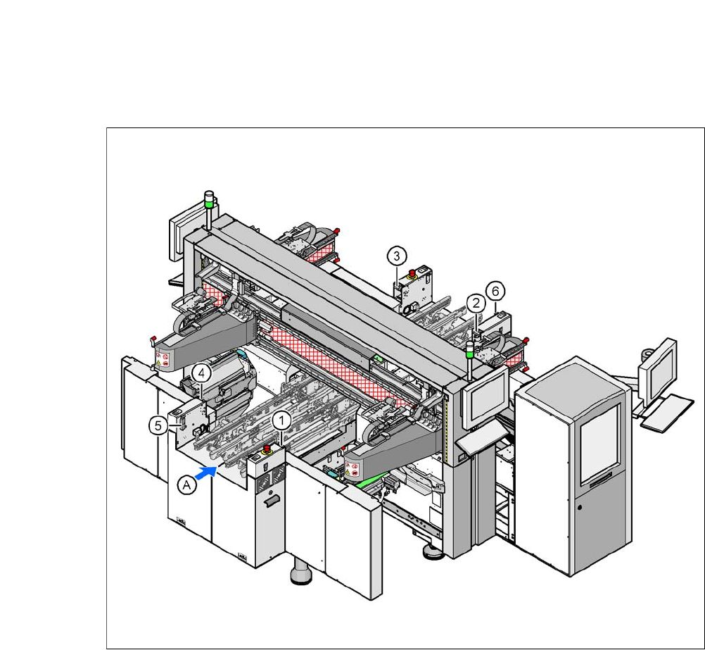
2.8.2.4 Position of Protective Switches on the Machine
2
Fig. 2.8 - 5 Position of protective switches on the machine
2
(1) Protective cover switch, location 1
(2) Protective cover switch, location 2
(3) Protective cover switch, location 3
(4) Protective cover switch, location 4
(5) Protective switch for the cover flap on the PCB conveyor input side
(6) Protective switch for the cover flap on the PCB conveyor output side
(A) PCB transport direction