00197498-03_UM_SiplaceCA-Serie_EN.pdf - 第92页
2 Operational Safety User Manual SIPLACE CA- Series 2.8 Safety Features From software version SC.708.0 Edition 12/2014 EN -DR AFT 92 Protective contactor combination 3TK2806 2 The prot ective contactor c ombination is co…
User Manual SIPLACE CA-Series 2 Operational Safety
From software version SC.708.0 Edition 12/2014 EN -DRAFT 2.8 Safety Features
91
2.8.3 Position of Protective Contactor Combination and Service Socket
2
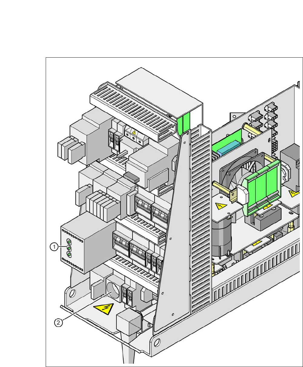
Fig. 2.8 - 6 Position of protective contactor combination and service socket
2
(1) Protective contactor combination
(2) Service socket
2 Operational Safety User Manual SIPLACE CA-Series
2.8 Safety Features From software version SC.708.0 Edition 12/2014 EN -DRAFT
92
Protective contactor combination 3TK2806 2
The protective contactor combination is contained in the power supply unit. It is used to monitor
the EMERGENCY STOP circuits and safety equipment.
There are three conditions that must be fulfilled in order to activate the protective contactor com-
bination:
– The "software enable" signal must have been sent.
– The EMERGENCY STOP loop must be closed.
– The start button must have been pressed.
The front side of the protective contactor combination has three green LEDs for the operating dis-
play (see fig. 2.8 - 7
, page 93):
– The "Mains" LED indicates that voltage is present.
– The "Channel 1" and "Channel 2" LEDs light up if the Start button was pressed, the EMER-
GENCY STOP circuit is closed and the signaling circuit is not signaling a fault status.
Service socket (item 2 in fig. 2.8 - 6) 2
The service socket is contained in the power supply unit and is protected by the cover. It can only
be used if the machine is connected to the main power supply via a 5-wire connection (L1, L2, L3,
N, and PE). If a 4-wire connection is used, e.g. without N, the socket cannot be used.
2
2.8.4 EMERGENCY STOP Loops and Signaling Circuit for SIPLACE and the SWS
The EMERGENCY STOP functionality of the SIPLACE has been enhanced by the EMERGENCY
OFF circuit of the SWS. For this reason the switching device 3TK2830-1CB30 (K6.1) has been
integrated into the power supply unit of the SIPLACE (see the plan "Extension of SIPLACE CA
EMERGENCY STOP" [00386139]).
WARNING
Safety instructions about lethal voltages!
Always follow the safety instructions concerning potentially lethal voltages - even when
the machine is switched off. (See section 2.1.3
from page 38)
User Manual SIPLACE CA-Series 2 Operational Safety
From software version SC.708.0 Edition 12/2014 EN -DRAFT 2.8 Safety Features
93
2.8.4.1 Structure of SIPLACE EMERGENCY STOP Loops
The following contacts are connected in series and form the EMERGENCY STOP loop:
– Make contact elements for the four protective cover switches
– Normally open (NO) contacts in the two protective switches for the cover flaps over the PCB
conveyor
– Make contact elements for the two EMERGENCY STOP buttons
– Normally open (NO) contacts for the feeder module cover flaps (option)
– Make contacts for the four component trolleys or SWS modules (wafer feeders)
– Channels for the protective contactor combination SSK K6 and extension K6.1 (3TK2830-
1CB30)
In EMERGENCY STOP loop 2, the CAN bus signal of the signaling circuit (see section 2.8.4.2
) is
fed to channel 2 of protective contactor combination SSK K6. If the EMERGENCY STOP circuit is
closed, and the signaling circuit is not signaling a malfunction, then the two green LEDs for chan-
nels 1 and 2 light up, in addition to the green mains power check LED of the protective contactor
combination.
2
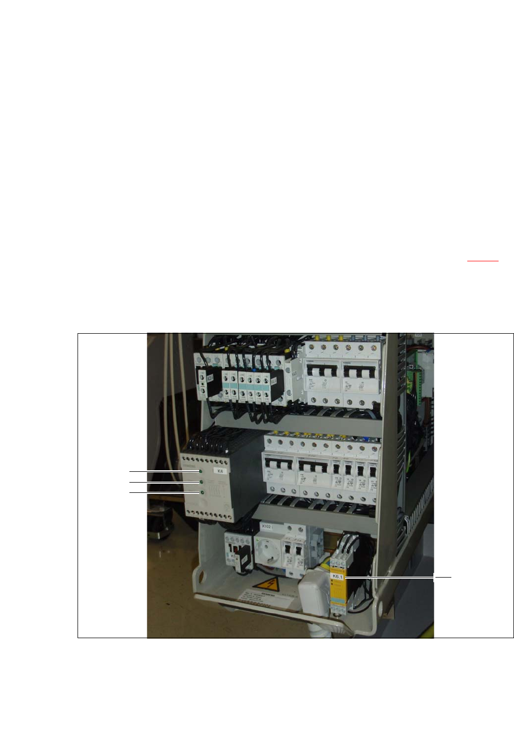
Fig. 2.8 - 7 Signal LED on the protective contactor combination K6 and SWS EMERGENCY STOP switching device
K6.1
(1) Mains / Power
(2) Kanal 1 / Channel 1
(3) Kanal 2 / Channel 2
(4) SWS EMERGENCY STOP switching device
extension K6.1 (3TK2830-1CB30)
1
2
3
4