00197498-03_UM_SiplaceCA-Serie_EN.pdf - 第97页
User Manual SIPLACE CA-Series 2 Operational Safety From software version SC.708.0 Edition 12/20 14 EN -DRAFT 2.8 Safety Features 97 In these cases the SIPLACE and the SWS EMERGENCY ST OP circuits are inte rrupted and the…

2 Operational Safety User Manual SIPLACE CA-Series
2.8 Safety Features From software version SC.708.0 Edition 12/2014 EN -DRAFT
96
2.8.4.4 Structure and Control of SWS EMERGENCY STOP Loops
The following input and output signals control the EMERGENCY STOP circuit:
– Input 1 = 1 > EMERGENCY STOP button on the SWS is not pressed
– Input 16 = 1 > SWS EMERGENCY STOP circuit for switching device K3 is closed
– Input 1 = 0 / IN16 = 0 > EMERGENCY STOP activation of the SWS (internal)
– Input 1 = 1 / IN16 = 0 > EMERGENCY STOP activation of the SWS (external)
– Input 15= 1 > Contactors K1/K2 = on, 48 V DC control for the motor amplifiers = OK
– Output 1 = K4 (on/off 150 ms) > Resetting EMERGENCY STOP > Starting SWS
– Output 16 = 1 > K5 = On "Feeder Present" signal to the SIPLACE
2.8.4.5 Function of the SWS EMERGENCY STOP Loop
The following conditions must be fulfilled to ensure that the EMERGENCY STOP switching device
K3 is enabled after the SWS is switched on:
– The SWS EMERGENCY STOP circuit is closed, i.e. the EMERGENCY STOP button on the
SWS is not pressed.
– The SIPLACE- EMERGENCY STOP circuit is closed, i.e. the protective cover is closed and
the start button is pressed.
– The initial condition of the inputs IN1 and IN16 is 1.
After that, the reset / start circuit is closed (by means of output 1 = K4 (on/off 150 ms) > resetting
the SWS EMERGENCY STOP).
–The K1/K2 contactors are switched on (24 V DC loop).
– The link voltage of 48 V DC to the motor amplifiers DMC-19540(20) is supplied.
– The motor voltage is activated afterwards via the Enable signal from the motor controller.
– The ABORT signal (motor amplifier DMC-19540(20)) is disabled via the K2 break contact.
– A 24 V DC EMERGENCY STOP voltage is supplied.
– The compressed air main valve Y1/PRS for the die ejector lift is switched on.
– The operating status indicator (white) on the SWS is switched on.
The SWS is ready to operate.
Enabling the EMERGENCY STOP
An EMERGENCY STOP can be triggered by:
– Pressing the EMERGENCY STOP button on the SWS.
– Pressing the EMERGENCY STOP button on the placement machine.
– Opening one of the protective covers of the placement machine.

User Manual SIPLACE CA-Series 2 Operational Safety
From software version SC.708.0 Edition 12/2014 EN -DRAFT 2.8 Safety Features
97
In these cases the SIPLACE and the SWS EMERGENCY STOP circuits are interrupted and the
corresponding EMERGENCY STOP switching devices switch the contactors off (delayed by 500
ms). Thus, there is a remaining time for a controlled stop function:
– The 48 V link voltage for the servo motors is switched off.
– The operating status indicator (white) on the SWS is switched off.
– The compressed air main valve Y1/PRS for the die ejector lift is switched off.
– The compressed air valves of the cylinders for tool Z (pickup) and tool X (die attach unit) are
switched off.
– The drives are switched off and the tools are held in a secure position by means of spring
elasticity.
– The braking magnet for the magazine lift function is switched off. The brake is active and the
magazine lift is held in position.
Resetting an EMERGENCY STOP
To reset an EMERGENCY STOP the EMERGENCY STOP circuits of the SIPLACE and the SWS
must be closed again.
– Release the pressed EMERGENCY STOP button on the SWS or the placement machine.
– Close any opened protective covers on the placement machine.
Switch the SWSs and the placement machine on.
The modules are starting up. As long as the placement machine is not yet switched on, an
error message will be displayed on the screen of the SWS module, which points out that the
safety circuit is not closed.
As soon as the placement machine has started up, the start circuit is closed (by means of out-
put 1 = K4 (on/off 150 ms). The error message regarding the not-closed safety circuit van-
ishes from the SWSs. Initialize the SWS module.
2 Operational Safety User Manual SIPLACE CA-Series
2.8 Safety Features From software version SC.708.0 Edition 12/2014 EN -DRAFT
98
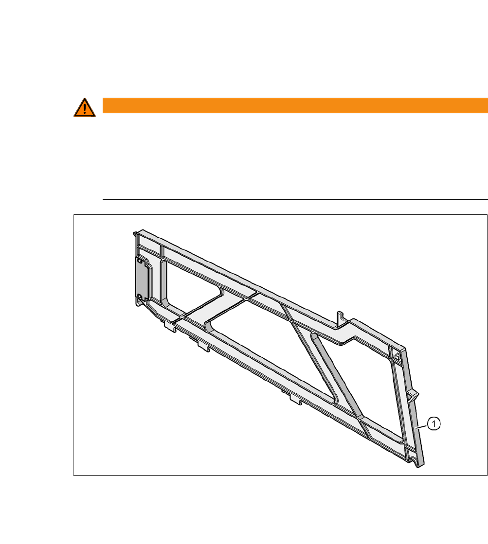
2.8.5 Hand Guard on the Locations for the Component Trolley, SIPLACE X-Series
2
Fig. 2.8 - 9 Hand guard on the component trolley locations, SIPLACE X-Series
2
(1) Hand guard for 1 location [03028842-01]
The hand guard occupies an 8 mm - location and can be changed during placement operations.
WARNING
Operational
Operational safety by occupying every second location!
The operational safety of the component trolley in the SIPLACE X-Series is ensured if at
least every second free location is occupied with a feeder module or a hand guard (dum-
my feeder).
Even when configuring a holder for waffle pack trays, secure every second location
with a hand guard.