00192328-01.pdf - 第55页
SIPLACE S-25 HM 2 Retrofitt. Instruct. RV6-DLM1 Head & Nozzle Chang. RV6 Standa rd (Optionen) 02/01 Issue 2.4 Sequence: Ins talling the Hardware 53 6HTXH QFH,Q VW DOOLQJ WKH+DUGZ DUH < RXZLOOUHTXLU H – …

2 Retrofitt. Instruct. RV6-DLM1 Head & Nozzle Chang. RV6 Standard (Optionen) SIPLACE S-25 HM
2.3 Retrofitting Kits, Tool and Documents 02/01 Issue
52
5HTXLUHG'RFXPHQWV
– Software Version Description for Station V 502.01, Item no. 00192395-01 (G + E)
– Software Guide SITEST V 502.xx, Item no. 00192656-01 (E)
– Software Version Description, LRU V 502.01, Item no. 00192397-01 (G + E)
– For preparing the 6-segment revolver head, modular:
Conversion Instructions DLM1 Collect & Place Head, Item no. 00191684-0 (G + E).
– For Setting the Dynamic:
Setting Instructions for SIPLACE S-25 HM, Item no. 00192192-02 (G + E)
– For nozzle changer RV6 MTC:
Retrofitting Instructions for MTC on S-25 HM, Item no. 00192792-02 (G + E)
NOTE:
These instructions contain the retrofitting of the nozzle changer RV6 Standard (for 6-segment re-
volver head DLM1) -> see Section 2.4.5.

SIPLACE S-25 HM 2 Retrofitt. Instruct. RV6-DLM1 Head & Nozzle Chang. RV6 Standard (Optionen)
02/01 Issue 2.4 Sequence: Installing the Hardware
53
6HTXHQFH,QVWDOOLQJWKH+DUGZDUH
<RXZLOOUHTXLUH
– Conversion Instructions, Item no. 00191684-03 (G + E)
– Conversion kit "6 C&P-head R-configuration kit" (option), Item no. 00117261-01
NOTE:
The document "Conversion Instructions.." describes the preparation of the new head (raising of
the vacuum generator and the fastening of the ribbon cables).
This is supplemented by the following description of the entire process including de-installation
and installation.
3UHSDUDWRU\6WHSV
CAUTION
When installing the RV6-DLM1 head during upgrading S-23 HM to SW V 502.01, you have to push
the gantry/placement head in a position over the PCB conveyor area (see retrofitting instructions,
Item no. 00192377-01).
The function for the change of the component table - All axes in set-up position - exists only with
Version 502.01 and later.
Å On S-25 HM select the function "All axes in set-up position" for changing the component table.
Å Undock the movable component changeover table from the machine and move it out of the
machine.
Å Turn the machine OFF; isolate it from the mains; turn the compressed air OFF at the com-
pressed air unit and bleed the needle valve on the compressed air unit (see DANGER text in
Section 2.2).
2 Retrofitt. Instruct. RV6-DLM1 Head & Nozzle Chang. RV6 Standard (Optionen) SIPLACE S-25 HM
2.4 Sequence: Installing the Hardware 02/01 Issue
54
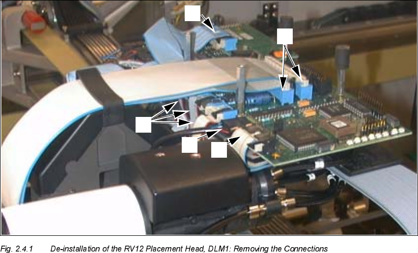
'H,QVWDOOLQJ6HJPHQW5HYROYHU+HDG59'/0
.H\
1. Ribbon cable "Vacuum board"
2. Round cable "Revolver head" (motor, tachometer)
3. 3 ribbon cables "Stepped motors/Photoelectric barrier"
4. 1 ribbon cable "Illumination PCB camera (illlumination board)
5. 2 ribbon cables, wide
Å Remove the 4 protective covers from the placement head: Unscrew the socket hex head cap
screws M3 and M2.5.
Å Undo the connectors of the front part of the placement head at the "Conversion board, small
axis" and on the illumination board (see: Fig. 2.4.1 -> 1 to 5).