00192328-01.pdf - 第58页
2 Retrofitt. Instruct. RV6-DLM1 Head & Nozzle Chang. RV6 Standard (Optionen) S IPLACE S-25 HM 2.4 Sequence: Inst alling the Hardware 02/01 Issue 56 .H\ 1. Compress ed air feeder to the vac uum g enerator (5 hose s…
2 Retrofitt. Instruct. RV6-DLM1 Head & Nozzle Chang. RV6 Standard (Optionen) SIPLACE S-25 HM
2.4 Sequence: Installing the Hardware 02/01 Issue
56
.H\
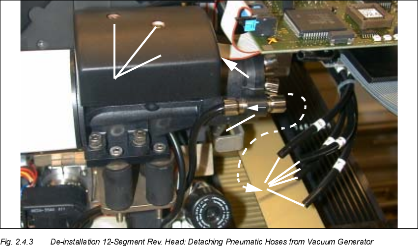
1. Compressed air feeder to the vacuum generator (5 hoses)
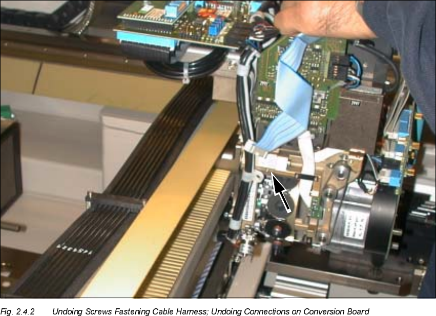
2. Collar on compressed air connection to the blast unit (support while pulling hoses off).
3. Cover over vacuum distributor board
(Fasteners: 2 socket hex head cap screws M2.5)
4. Ribbon cable: Connection on vacuum distributor board
Å Pull off the 5 compressed air hoses on the vacuum generator (see: Fig. 2.4.3).
Support in the case of the quick-release coupling (-> 2).
Å Remove the cover from the vacuum distributor board (loosen 2 socket hex head cap screws
M2.5, size 3).
Å Pull the 2 silicone hoses off the vacuum distributor board.
Å Pull the 2 silicone hoses off the silencer.
Å Support the placement head:
Undo the screws fastening the placement head: 3 socket hex head cap screws M4.
The head is still held in position by pins.
Å Pull the placement head (pins in the part to be pulled off) off the back part and set it down such
that it is not damaged, preferably in the proper package.
SIPLACE S-25 HM 2 Retrofitt. Instruct. RV6-DLM1 Head & Nozzle Chang. RV6 Standard (Optionen)
02/01 Issue 2.4 Sequence: Installing the Hardware
57
3UHSDULQJWKH1HZ6HJPHQW5HYROYHU+HDG59'/0
NOTE:
The document "Conversion Instructions" Item no
. 00191684-03 (D + E) describes the preparation
of the new head (raising of the vacuum generator and the fastening of the ribbon cables).
This is supplemented by the following description of the entire process including de-installation
and installation.
.H\
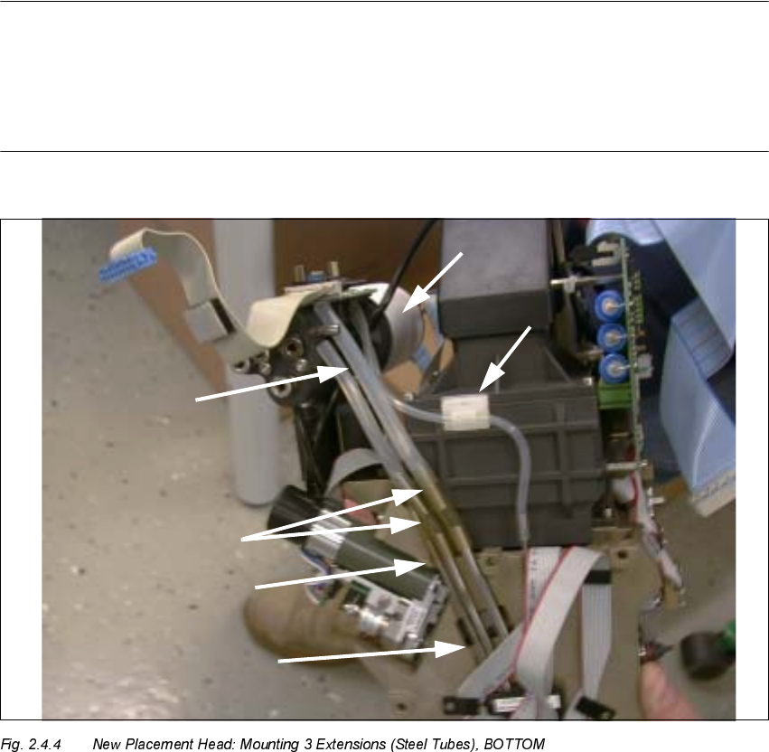
1. Vacuum generator with silencer (fasteners: 4 socket hex head cap screws M4)
2. Silicone hoses am the vacuum distributor
3. NEW extension to be installed:
2 tubes 35 mm long (enclosed package in the retrofit kit, see: Section 2.3)
4. NEW extension to be installed:
1 tube 30 mm long (enclosed package in the retrofit kit, see: Section 2.3)
5. Vacuum feeders to the star (metal tube, fixed).
6. Vacuum hose, fastened with round-cable clamp (vacuum check for holding circuit)